Installation
To calculate the AXlink wiring distance formula for data and power:
1.<Total current consumption of all device's on AXlink cable> *<wire resistance per foot> * 2 = <voltage drop per foot>. See tables below for the Wire Resistance/Foot values.
2.<Power supply voltage> - 12 VDC = <surplus voltage dissipation for cable run>.
3.<Surplus voltage dissipation for cable run> / < voltage drop per foot > = Maximum distance in feet.
The following table lists the resistance factors used in the formula.
Gauge/resistance factors - Solid Copper Wiring
Wire gauge | Wire Resistance/foot |
|
|
18 AWG | .00639 |
|
|
20 AWG | .0101 |
|
|
22 AWG | .0162 |
|
|
24 AWG | .0257 |
|
|
For further details on AxLink Wiring, refer to the AXlink Wiring Considerations Instruction Manual (available online at www.amx.com).
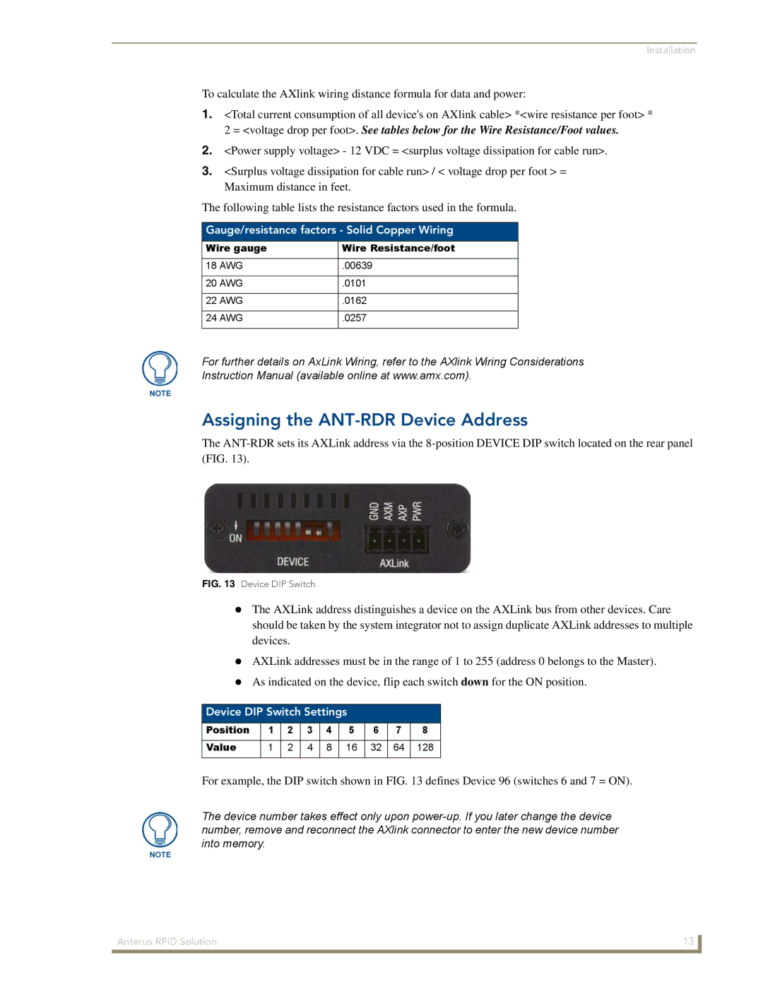
Assigning the ANT-RDR Device Address
The
FIG. 13 Device DIP Switch
The AXLink address distinguishes a device on the AXLink bus from other devices. Care should be taken by the system integrator not to assign duplicate AXLink addresses to multiple devices.
AXLink addresses must be in the range of 1 to 255 (address 0 belongs to the Master).
As indicated on the device, flip each switch down for the ON position.
Device DIP Switch Settings
Position | 1 | 2 | 3 | 4 | 5 | 6 | 7 | 8 |
|
|
|
|
|
|
|
|
|
Value | 1 | 2 | 4 | 8 | 16 | 32 | 64 | 128 |
|
|
|
|
|
|
|
|
|
For example, the DIP switch shown in FIG. 13 defines Device 96 (switches 6 and 7 = ON).
The device number takes effect only upon
Anterus RFID Solution | 13 |
|
|