ViewStat specifications
AMX ViewStat is a revolutionary thermostat solution designed for both residential and commercial environments, providing robust control over heating, ventilation, and air conditioning (HVAC) systems. This intelligent device stands out for its user-friendly interface, advanced technology integration, and versatility in various settings.One of the main features of AMX ViewStat is its intuitive touch screen interface, which enables users to easily navigate through settings and preferences. This 4.3-inch color display not only enhances usability but also allows for customization, offering users the ability to personalize the user experience according to their lifestyle and preferences. Whether adjusting temperature settings or scheduling heating/cooling cycles, the interface ensures a seamless interaction.
Among its key technological advancements is the integration of Wi-Fi connectivity. By connecting to a home or building's network, users can remotely access and control the thermostat through a smartphone, tablet, or computer. This level of control facilitates energy savings, as users can monitor and adjust settings from anywhere, leading to optimized usage and reduced utility bills.
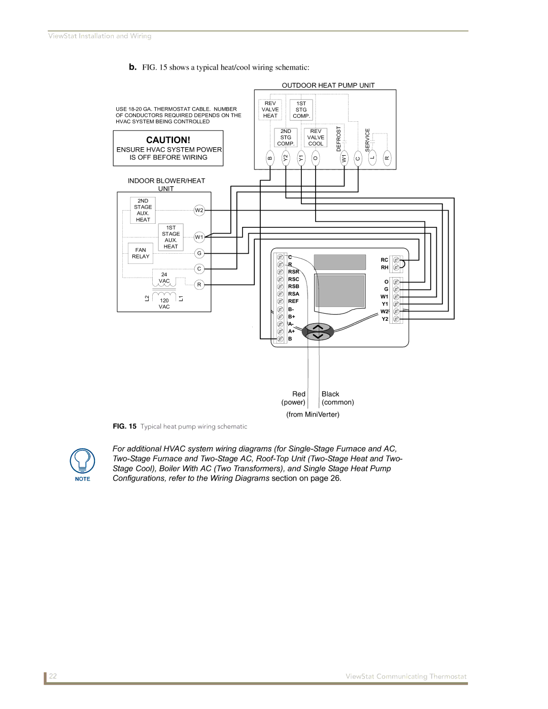
AMX ViewStat is compatible with various HVAC systems, accommodating both conventional and heat pump setups. Its flexibility in adapting to different configurations makes it suitable for diverse applications, from single-family homes to large commercial spaces.
Moreover, the device incorporates advanced energy management features, granting users insights into their energy usage patterns. This data-driven approach allows users to make informed decisions about their energy consumption, ultimately promoting a more sustainable lifestyle.
In addition to its primary functions, AMX ViewStat integrates with other AMX control solutions, enabling a centralized command for home or office automation. When combined with AMX automation systems, users can achieve a fully integrated environment where lighting, security, and entertainment systems work in harmony with heating and cooling controls.
The construction of AMX ViewStat is robust yet stylish, designed to fit seamlessly into any decor. Available in multiple finishes, it adds a touch of elegance while ensuring durability and functionality.
In conclusion, AMX ViewStat is a state-of-the-art thermostat solution that offers a blend of advanced technology, ease of use, and energy efficiency. With features like remote connectivity, compatibility with various HVAC types, and integration with broader automation systems, it stands as a comprehensive solution for modern living and working environments.

