Installation Procedures
Overview
Foundation Preparation
This section provides installation procedures for the
• Mount | • |
• Reflector | • Subreflector |
• Enclosure | • Feed System |
Before beginning the installation process on the ground mount assembly, ensure that the foundation has been prepared. Foundation specifications are provided by Andrew and may be used as a reference by civil engineering personnel when preparing the foundation for local soil conditions. These specifications are available before the ship- ment arrives by contacting the Customer Service Center or your Account Manager.
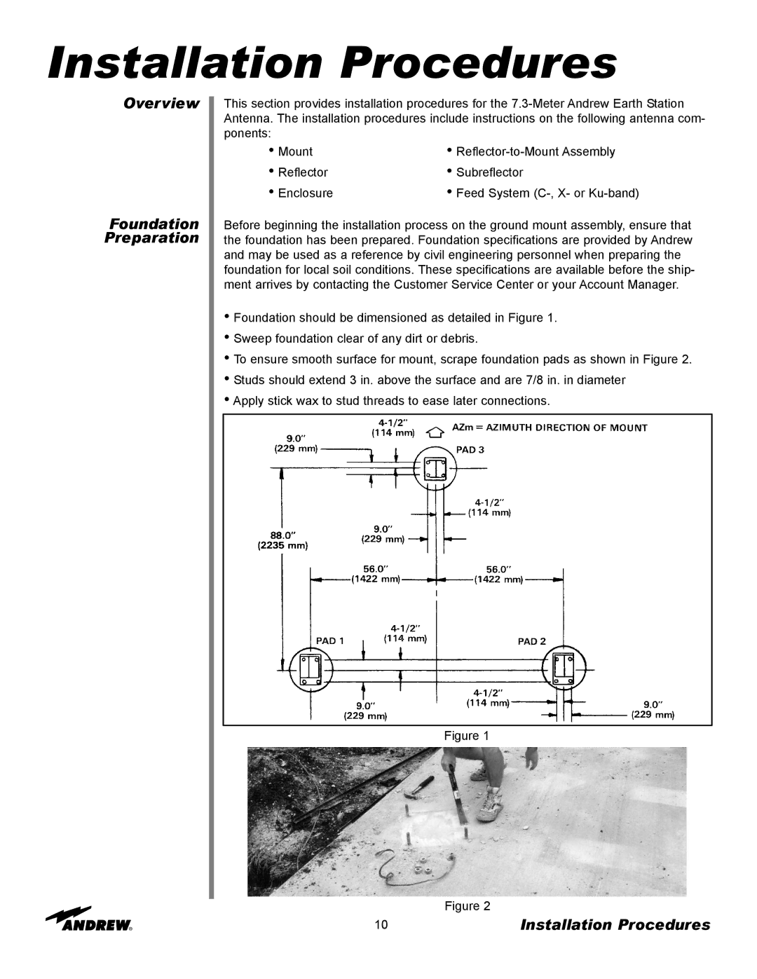
•Foundation should be dimensioned as detailed in Figure 1.
•Sweep foundation clear of any dirt or debris.
•To ensure smooth surface for mount, scrape foundation pads as shown in Figure 2.
•Studs should extend 3 in. above the surface and are 7/8 in. in diameter
•Apply stick wax to stud threads to ease later connections.
Figure 1
Figure 2
10 | Installation Procedures |