Step 2
Step 3
Step 4
Remove entire end of panel crate to allow easy access and careful removal of reflector panels.
•When transporting panels, support panel on side as packaged
Tie assembly down by knotting rope between lifting tabs and three 3 ft stakes as shown in Figure 45. This will prevent an unbalanced condition when adding panels one at a time.
Figure 45
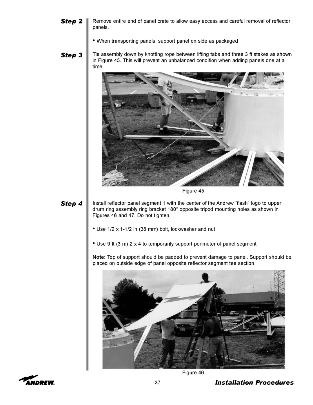
Install reflector panel segment 1 with the center of the Andrew “flash” logo to upper drum ring assembly ring bracket 180° opposite tripod mounting holes as shown in Figures 46 and 47. Do not tighten.
•Use 1/2 x
•Use 9 ft (3 m) 2 x 4 to temporarily support perimeter of panel segment
Note: Top of support should be padded to prevent damage to panel. Support should be placed on outside edge of panel opposite reflector segment tee section.
Figure 46
37 | Installation Procedures |