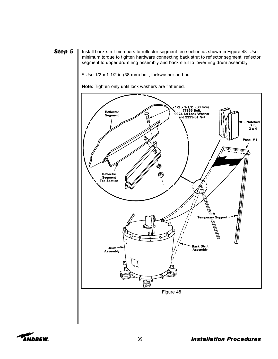
7.3-MeterEarth Station Antenna
Type ES73
Installation, Operation and Maintenance
7.3-MeterESA
Installation Procedures Operation Preventive
Table of Contents
Table of Contents
How to Use This Manual Getting Started
7.3-MeterEarth Station Antenna
Introduction
Introduction
24-hourTechnical Assistance
Customer Service Center
Proprietary Data Information and Assistance
Notice Technical Assistance
How to Use This Manual
Overview Content
How to Use This Manual
Getting Started
Overview Warnings
Getting Started
Quantity
Recommended Tools
Tool
Size
Concealed Damage Inventory Equipment Received
Parts Verification
Reporting Equipment Loss or Damage
Reporting Visible Loss or Damage Reporting
Getting Started
Returning Equipment Step Step Step Step Step
Installation Procedures
Overview Foundation Preparation
Installation Procedures
A-325Tensioning Step Step Step Step Step Step
Use Felt Marker Before After
Tensioning Tensioning
Tripod Ground Mount Assembly Azimuth Beam
Assembly Step Step Step
Installation Procedures
Support Legs Assembly Step Step
Installation Procedures
•Use 7/8 x 2-1/4in 57 mm bolts and nuts Figure
Installation Procedures
Step Step
Installation Procedures
Step Step
•Use 7/8 x 2-1/4in 57 mm bolts and nuts
Installation Procedures
Panning Frame Assembly Step
Figure Figure
Step
Installation Procedures
•Use 7/8 x 2-1/4in 57 mm hardware
Installation Procedures
Step Step
Figure
Installation Procedures
Step Step
•Use 7/8 x 2-1/4in 57 mm hardware
Installation Procedures
Step Step
•Use 7/8 x 2-1/4in 57 mm hardware
Figure
Installation Procedures
Elevation Axis Assembly
Step
Installation Procedures
Step Step
•Use 7/8 x 2-1/4in 57 mm bolt, flatwasher and nut
Installation Procedures
Elevation Jackscrew Assembly Step Step
Installation Procedures
Step Step
Figure
Azimuth Jackscrew Assembly Step Step
Mount Assembly Step Step
Installation Procedures
201327A 201313A
Installation Procedures
Step Step
Figure
Installation Procedures
Step Step
Figure 32A Figure 32B
Installation Procedures
Step Step Step
Installation Procedures
Step Step
Figure 35A
Reflector Subreflector Feed Assembly
Feed/Waveguide Assembly Step Step
Installation Procedures
Step
Figure
Installation Procedures
Step Step 5 Step
Figure
Installation Procedures
Step
•Insert bolts from feed horn to mounting pipe
Installation Procedures
Step
•Use 1/2 x 2 in 51 mm bolts, lockwashers and nuts
Installation Procedures
Step
Figure
Reflector Backstructure Assembly Step
Installation Procedures
Figure Figure
Installation Procedures
Step Step Step
Figure
Installation Procedures
Figure
Center portion of Andrew “flash” logo
Figure
Installation Procedures
Step
•Use 1/2 x 1-1/2in 38 mm bolt, lockwasher and nut
Installation Procedures
Step
Figure Figure
Figure
Installation Procedures
Step Step
Figure
Installation Procedures
Step Step Step Step Step Step
Installation Procedures
Step Step
Figure Figure
Subreflector Strut Assembly Step
Installation Procedures
Figure
Figure
Installation Procedures
Step
Figure Figure
Installation Procedures
Step Step Step
Figure
Installation Procedures
Reflector to Ground Mount Assembly Step Step
Figure Figure
Installation Procedures
Subreflector Assembly and Adjustment Step Step
Installation Procedures
Step Step
Figure
Installation Procedures
Cross-AxisGrounding Kit Step
Installation Procedures
Step Step Step
Figure
Operation
Overview Acquiring A Satellite
Operation
The following steps provide the procedure for acquiring a satellite
Step Step Step Step Step Step
Operation
Move the antenna in azimuth to obtain a null, then move ± in elevation to obtain a large peak signal. If not, move the antenna in the opposite azimuth direction through the peak and again move ± in elevation to obtain a large peak signal. If a larger peak is not found, you were on the main lobe
Step Step Step
Operation
Figure 4-4:Maximizing Odd Transponders
Figure 4-5:Optimum Polarization Setting
Step
Operation
Operation
Subreflector Adjustment
Preventive Maintenance
Overview General Cleaning Electrical Parts
Preventive Maintenance
Mechanical Parts Inspection Local Control/Motor
Drive Controller
Preventive Maintenance
Antenna
and minus direction from the local control/motor drive controller at least once every three months during antenna down time. Check the mechanical limit switches provided at the end points stop the antenna and feed movement, and limit travel to prevent struc- tural interference and damage. Check the mechanical limit switches for corrosion and water entry and the arm on each feed limit switch for free movement without binding. Be certain both feed rotation limit switch arms are not distorted and ride centrally on the actuating cam to open their corresponding limit switch
Preventive Maintenance
Drive System Voltage and Current Checks Step Step
Preventive Maintenance
Step
Preventive Maintenance
Turn the AZIMUTH EAST/WEST switch to either position and while the antenna is rotat- ing, carefully use a clamp on ammeter in accordance with the ammeter manufacturer’s instructions to take current readings off each of the three conductors phases connect- ed to the load side of the azimuth drive motor circuit breaker. Record the current draw in the equipment log and compare the readings to the reference values entered in the installation/acceptance check off. If the readings differ by more than five percent, refer to appropriate troubleshooting information and perform applicable corrective action. Then take voltage readings off each of the three conductors; the readings should agree with each other—withintwo percent
Step Step Step Step Step Step
Preservation of Component Parts Aluminum Parts
Galvanized Surfaces Lubrication
Preventive Maintenance
Jackscrews/Motors Gear Motor/Housing Fill Drain
Requirements
Preventive Maintenance
Lubrication Chart
Preventive Maintenance
5 9 10
6 7 8
High-SpeedAntenna Lubrication Points
6 7 8
Medium-SpeedAntenna Lubrication Points
Preventive Maintenance
5 9 10