Panning Frame Assembly
Step 1
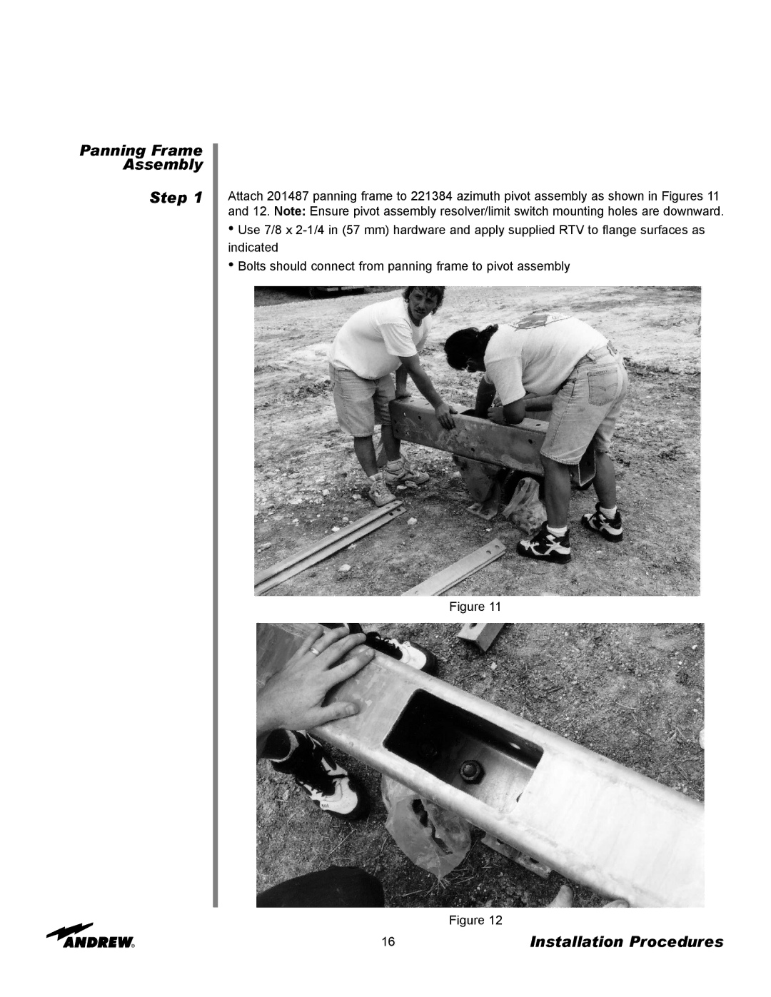
Attach 201487 panning frame to 221384 azimuth pivot assembly as shown in Figures 11 and 12. Note: Ensure pivot assembly resolver/limit switch mounting holes are downward.
•Use 7/8 x
•Bolts should connect from panning frame to pivot assembly
Figure 11
Figure 12
16 | Installation Procedures |
