Step 3
Step 4
Attach 201316 support pairs to 221608 joint assemblies as shown in Figure 15.
•Place supports
•Install 45967 spacer at midpoints of support pairs
•Use 7/8 x
201316
Supports
Figure 15
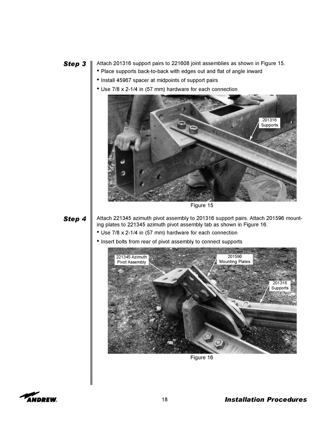
Attach 221345 azimuth pivot assembly to 201316 support pairs. Attach 201596 mount- ing plates to 221345 azimuth pivot assembly tab as shown in Figure 16.
•Use 7/8 x
•Insert bolts from rear of pivot assembly to connect supports
221345 Azimuth | 201596 |
Pivot Assembly | Mounting Plates |
201316
Supports
Figure 16
18 | Installation Procedures |