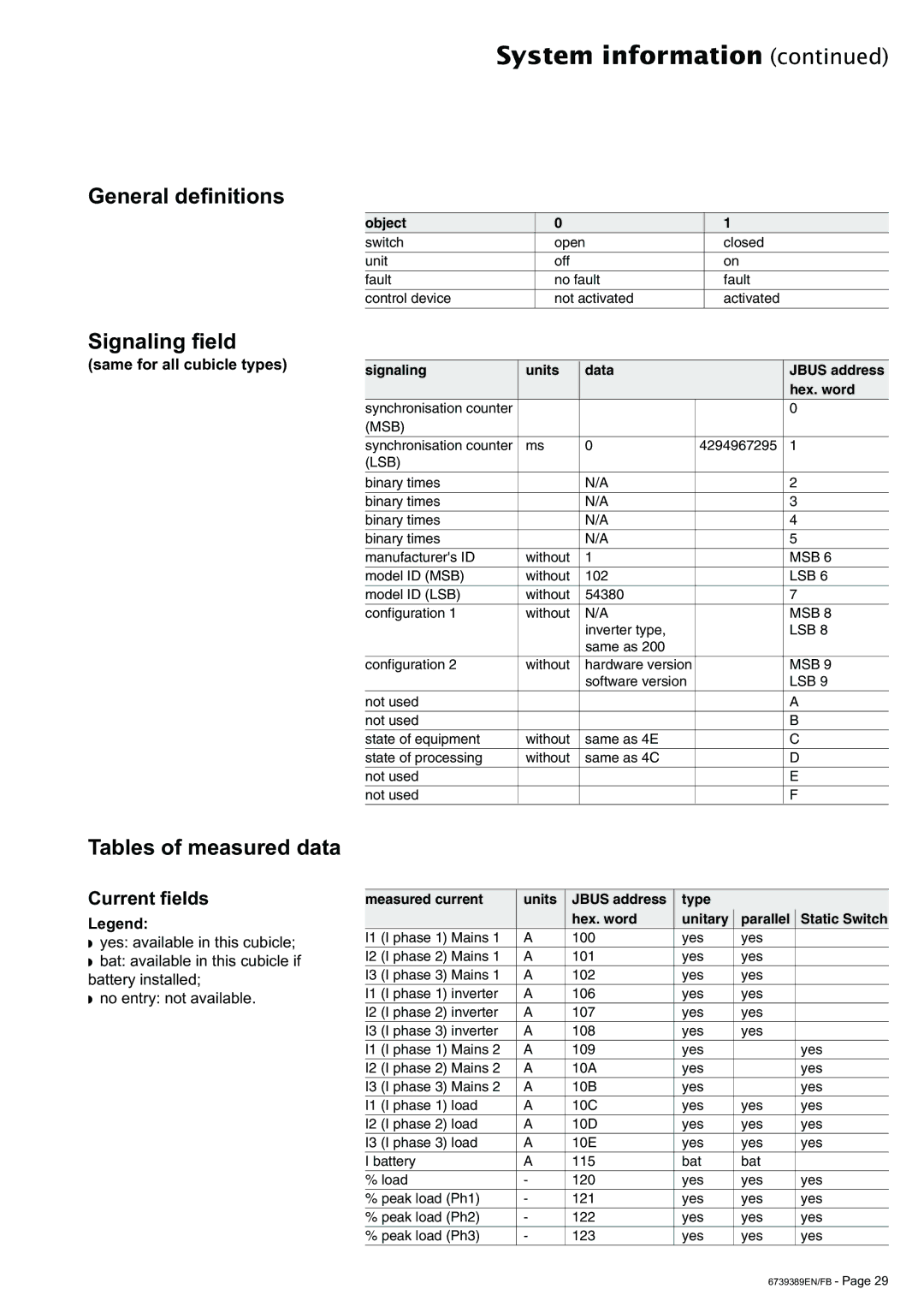
General definitions
Signaling field
(same for all cubicle types)
System information (continued)
object | 0 | 1 |
switch | open | closed |
|
|
|
unit | off | on |
|
|
|
fault | no fault | fault |
|
|
|
control device | not activated | activated |
|
|
|
signaling | units | data |
| JBUS address |
|
|
|
| hex. word |
synchronisation counter |
|
|
| 0 |
(MSB) |
|
|
|
|
synchronisation counter | ms | 0 | 4294967295 | 1 |
(LSB) |
|
|
|
|
|
|
|
|
|
binary times |
| N/A |
| 2 |
binary times |
| N/A |
| 3 |
binary times |
| N/A |
| 4 |
binary times |
| N/A |
| 5 |
manufacturer's ID | without | 1 |
| MSB 6 |
model ID (MSB) | without | 102 |
| LSB 6 |
model ID (LSB) | without | 54380 |
| 7 |
configuration 1 | without | N/A |
| MSB 8 |
|
| inverter type, |
| LSB 8 |
|
| same as 200 |
|
|
|
|
|
|
|
configuration 2 | without | hardware version |
| MSB 9 |
|
| software version |
| LSB 9 |
|
|
|
|
|
not used |
|
|
| A |
not used |
|
|
| B |
state of equipment | without | same as 4E |
| C |
state of processing | without | same as 4C |
| D |
not used |
|
|
| E |
not used |
|
|
| F |
Tables of measured data
Current fields | measured current | units | JBUS address | type |
|
| ||
Legend: |
|
|
| hex. word | unitary | parallel | Static Switch | |
|
|
|
|
|
|
| ||
◗ | yes: available in this cubicle; | I1 | (I phase 1) Mains 1 | A | 100 | yes | yes |
|
|
|
|
|
|
|
| ||
I2 | (I phase 2) Mains 1 | A | 101 | yes | yes |
| ||
◗ | bat: available in this cubicle if |
| ||||||
|
|
|
|
|
|
| ||
I3 | (I phase 3) Mains 1 | A | 102 | yes | yes |
| ||
battery installed; |
| |||||||
|
|
|
|
|
|
| ||
I1 | (I phase 1) inverter | A | 106 | yes | yes |
| ||
◗ | no entry: not available. |
| ||||||
|
|
|
|
|
|
| ||
I2 | (I phase 2) inverter | A | 107 | yes | yes |
| ||
|
|
| ||||||
|
|
|
|
|
|
|
|
|
|
| I3 | (I phase 3) inverter | A | 108 | yes | yes |
|
|
|
|
|
|
|
|
|
|
|
| I1 | (I phase 1) Mains 2 | A | 109 | yes |
| yes |
|
|
|
|
|
|
|
|
|
|
| I2 | (I phase 2) Mains 2 | A | 10A | yes |
| yes |
|
|
|
|
|
|
|
|
|
|
| I3 | (I phase 3) Mains 2 | A | 10B | yes |
| yes |
|
|
|
|
|
|
|
|
|
|
| I1 | (I phase 1) load | A | 10C | yes | yes | yes |
|
|
|
|
|
|
|
|
|
|
| I2 | (I phase 2) load | A | 10D | yes | yes | yes |
|
|
|
|
|
|
|
|
|
|
| I3 | (I phase 3) load | A | 10E | yes | yes | yes |
|
|
|
|
|
|
|
| |
|
| I battery | A | 115 | bat | bat |
| |
|
|
|
|
|
|
|
| |
|
| % load | - | 120 | yes | yes | yes | |
|
|
|
|
|
|
|
| |
|
| % peak load (Ph1) | - | 121 | yes | yes | yes | |
|
|
|
|
|
|
|
| |
|
| % peak load (Ph2) | - | 122 | yes | yes | yes | |
|
|
|
|
|
|
|
| |
|
| % peak load (Ph3) | - | 123 | yes | yes | yes | |
6739389EN/FB - Page 29