System information
Message format
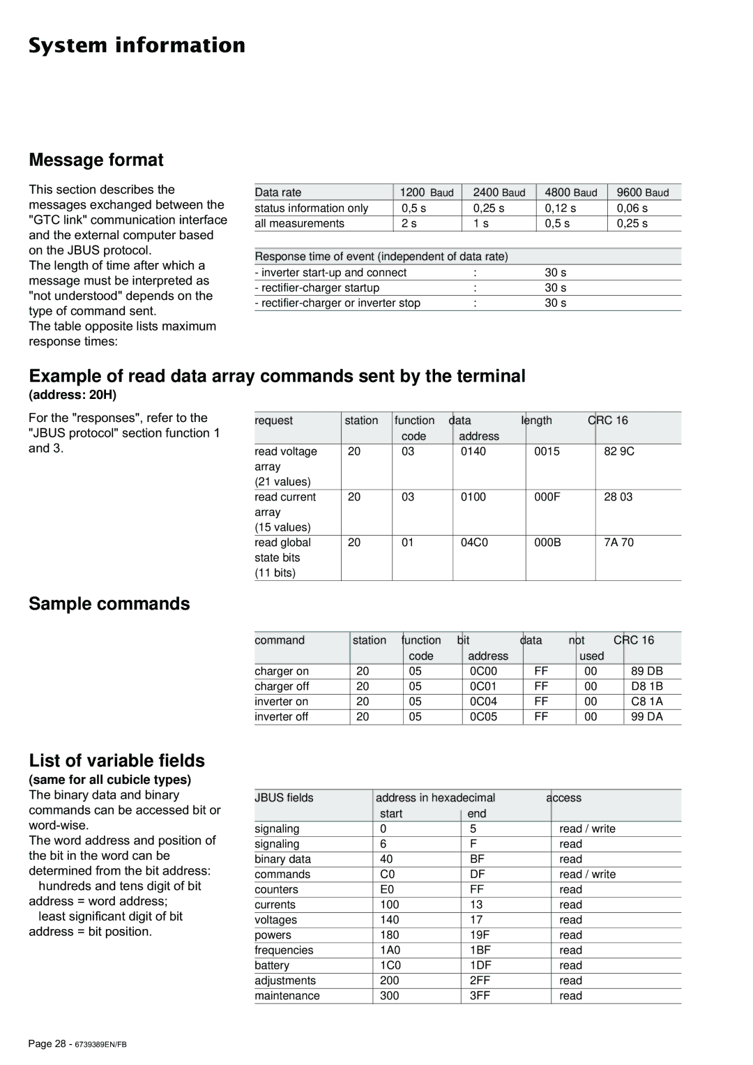
This section describes the messages exchanged between the "GTC link" communication interface and the external computer based on the JBUS protocol.
The length of time after which a message must be interpreted as "not understood" depends on the type of command sent.
The table opposite lists maximum response times:
Data rate | 1200 Baud | 2400 Baud | 4800 Baud | 9600 Baud |
status information only | 0,5 s | 0,25 s | 0,12 s | 0,06 s |
|
|
|
|
|
all measurements | 2 s | 1 s | 0,5 s | 0,25 s |
|
|
|
|
|
|
|
|
|
|
Response time of event (independent of data rate) |
|
| ||
- inverter | : | 30 s |
| |
|
|
|
|
|
- |
| : | 30 s |
|
|
|
|
| |
- | : | 30 s |
| |
|
|
|
|
|
Example of read data array commands sent by the terminal
(address: 20H)
For the "responses", refer to the "JBUS protocol" section function 1 and 3.
request | station | function | data | length | CRC 16 |
|
| code | address |
|
|
read voltage | 20 | 03 | 0140 | 0015 | 82 9C |
array |
|
|
|
|
|
(21 values) |
|
|
|
|
|
read current | 20 | 03 | 0100 | 000F | 28 03 |
array |
|
|
|
|
|
(15 values) |
|
|
|
|
|
read global | 20 | 01 | 04C0 | 000B | 7A 70 |
state bits |
|
|
|
|
|
(11 bits) |
|
|
|
|
|
Sample commands
List of variable fields
(same for all cubicle types)
The binary data and binary commands can be accessed bit or
The word address and position of the bit in the word can be determined from the bit address:
◗hundreds and tens digit of bit address = word address;
◗least significant digit of bit address = bit position.
command | station | function | bit | data | not | CRC 16 |
|
| code | address |
| used |
|
charger on | 20 | 05 | 0C00 | FF | 00 | 89 DB |
|
|
|
|
|
|
|
charger off | 20 | 05 | 0C01 | FF | 00 | D8 1B |
|
|
|
|
|
|
|
inverter on | 20 | 05 | 0C04 | FF | 00 | C8 1A |
|
|
|
|
|
|
|
inverter off | 20 | 05 | 0C05 | FF | 00 | 99 DA |
|
|
|
|
|
|
|
| JBUS fields | address in hexadecimal | access | ||
|
| start |
| end |
|
|
|
|
| ||
| signaling | 0 |
| 5 | read / write |
signaling | 6 |
| F | read | |
binary data | 40 |
| BF | read | |
commands | C0 |
| DF | read / write | |
counters | E0 |
| FF | read | |
currents | 100 |
| 13 | read | |
voltages | 140 |
| 17 | read | |
powers | 180 |
| 19F | read | |
frequencies | 1A0 |
| 1BF | read | |
battery | 1C0 |
| 1DF | read | |
adjustments | 200 |
| 2FF | read | |
maintenance | 300 |
| 3FF | read | |
Page 28 - 6739389EN/FB