JBUS protocol (continued)
Principle
A full understanding of the protocol is only required if the master is a computer that must be programmed.
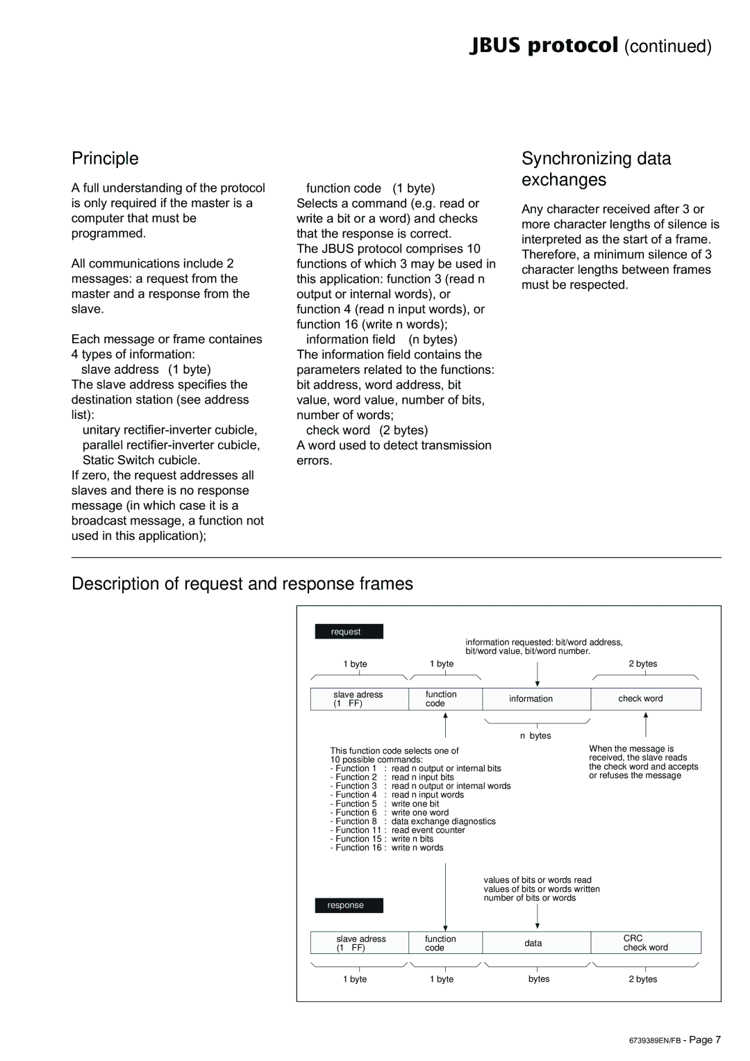
All communications include 2 messages: a request from the master and a response from the slave.
Each message or frame containes
4 types of information:
◗slave address (1 byte)
The slave address specifies the destination station (see address list):
◗unitary
◗parallel
◗Static Switch cubicle.
If zero, the request addresses all slaves and there is no response message (in which case it is a broadcast message, a function not used in this application);
◗function code (1 byte) Selects a command (e.g. read or write a bit or a word) and checks that the response is correct.
The JBUS protocol comprises 10 functions of which 3 may be used in this application: function 3 (read n output or internal words), or function 4 (read n input words), or function 16 (write n words);
◗information field (n bytes)
The information field contains the parameters related to the functions: bit address, word address, bit value, word value, number of bits, number of words;
◗check word (2 bytes)
A word used to detect transmission errors.
Synchronizing data exchanges
Any character received after 3 or more character lengths of silence is interpreted as the start of a frame. Therefore, a minimum silence of 3 character lengths between frames must be respected.
Description of request and response frames
request
information requested: bit/word address, bit/word value, bit/word number.
1 byte | 1 byte |
|
| |
|
| |||
|
|
|
| |
|
|
|
| |
slave adress | function | information | ||
(1 à FF) | code | |||
|
| |||
|
|
|
| |
n bytes
This function code selects one of
10 possible commands:
-Function 1 : read n output or internal bits
-Function 2 : read n input bits
-Function 3 : read n output or internal words
-Function 4 : read n input words
-Function 5 : write one bit
-Function 6 : write one word
-Function 8 : data exchange diagnostics
-Function 11 : read event counter
-Function 15 : write n bits
-Function 16 : write n words
2bytes
check word
When the message is received, the slave reads the check word and accepts or refuses the message
response
values of bits or words read values of bits or words written number of bits or words
slave adress (1 à FF)
function code
data
CRC check word
1 byte | 1 byte | ◗ bytes | 2 bytes |
6739389EN/FB - Page 7
