When one active Local Controller becomes unreachable, APs connected to the unreachable controller fail over to the standby Local Controller loading that controller to 100% capacity. Therefore each controller must have sufficient processing power and licenses to accommodate all of the APs served by the entire cluster. In this model, preemption should be enabled to force the APs to fail back to the original primary when it comes back online.
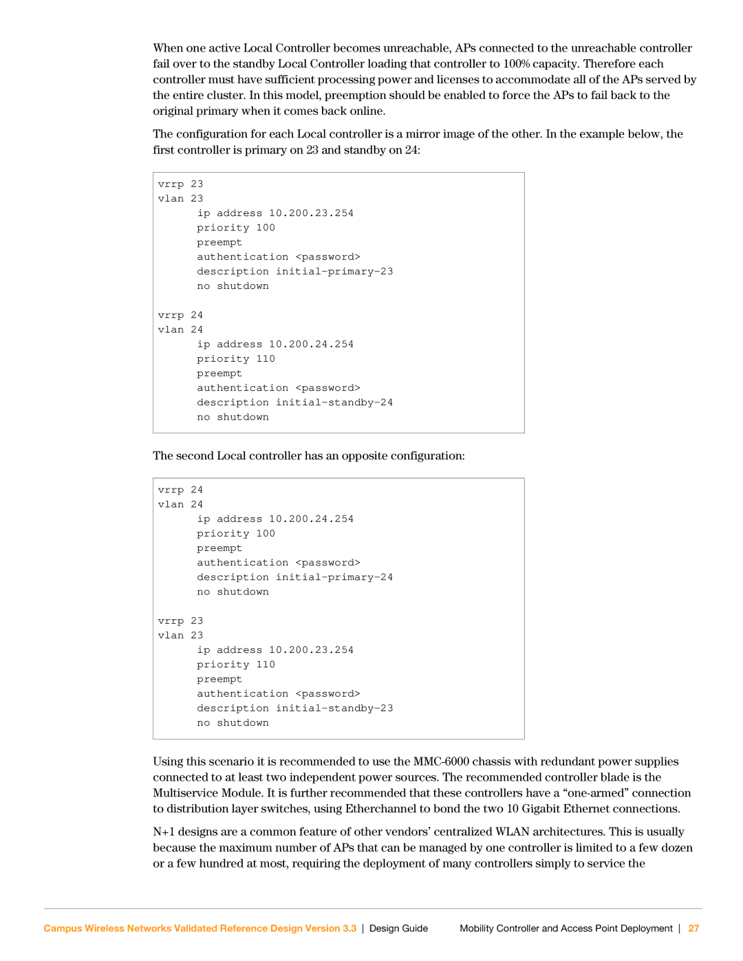
The configuration for each Local controller is a mirror image of the other. In the example below, the first controller is primary on 23 and standby on 24:
vrrp 23 vlan 23
ip address 10.200.23.254 priority 100
preempt
authentication <password> description
vrrp 24 vlan 24
ip address 10.200.24.254 priority 110
preempt
authentication <password> description
The second Local controller has an opposite configuration:
vrrp 24 vlan 24
ip address 10.200.24.254 priority 100
preempt
authentication <password> description
vrrp 23 vlan 23
ip address 10.200.23.254 priority 110
preempt
authentication <password> description
Using this scenario it is recommended to use the
N+1 designs are a common feature of other vendors’ centralized WLAN architectures. This is usually because the maximum number of APs that can be managed by one controller is limited to a few dozen or a few hundred at most, requiring the deployment of many controllers simply to service the
Campus Wireless Networks Validated Reference Design Version 3.3 Design Guide | Mobility Controller and Access Point Deployment 27 |