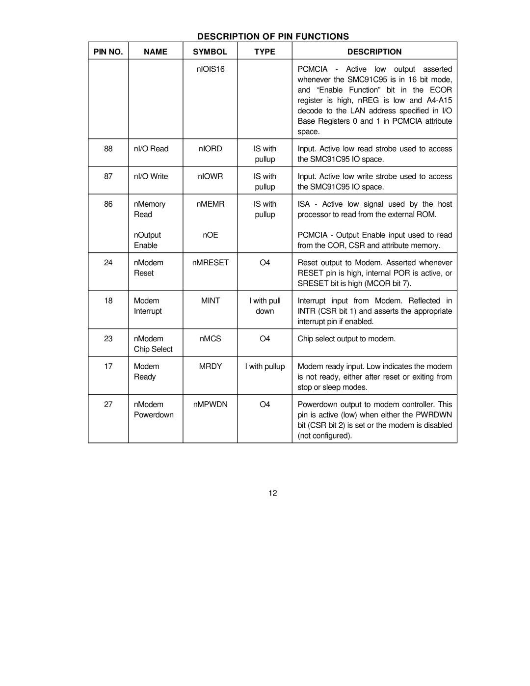
DESCRIPTION OF PIN FUNCTIONS
PIN NO. | NAME | SYMBOL | TYPE | DESCRIPTION |
|
|
|
|
|
|
| nIOIS16 |
| PCMCIA - Active low output asserted |
|
|
|
| whenever the SMC91C95 is in 16 bit mode, |
|
|
|
| and “Enable Function” bit in the ECOR |
|
|
|
| register is high, nREG is low and |
|
|
|
| decode to the LAN address specified in I/O |
|
|
|
| Base Registers 0 and 1 in PCMCIA attribute |
|
|
|
| space. |
|
|
|
|
|
88 | nI/O Read | nIORD | IS with | Input. Active low read strobe used to access |
|
|
| pullup | the SMC91C95 IO space. |
|
|
|
|
|
87 | nI/O Write | nIOWR | IS with | Input. Active low write strobe used to access |
|
|
| pullup | the SMC91C95 IO space. |
|
|
|
|
|
86 | nMemory | nMEMR | IS with | ISA - Active low signal used by the host |
| Read |
| pullup | processor to read from the external ROM. |
| nOutput | nOE |
| PCMCIA - Output Enable input used to read |
| Enable |
|
| from the COR, CSR and attribute memory. |
|
|
|
|
|
24 | nModem | nMRESET | O4 | Reset output to Modem. Asserted whenever |
| Reset |
|
| RESET pin is high, internal POR is active, or |
|
|
|
| SRESET bit is high (MCOR bit 7). |
|
|
|
|
|
18 | Modem | MINT | I with pull | Interrupt input from Modem. Reflected in |
| Interrupt |
| down | INTR (CSR bit 1) and asserts the appropriate |
|
|
|
| interrupt pin if enabled. |
|
|
|
|
|
23 | nModem | nMCS | O4 | Chip select output to modem. |
| Chip Select |
|
|
|
|
|
|
|
|
17 | Modem | MRDY | I with pullup | Modem ready input. Low indicates the modem |
| Ready |
|
| is not ready, either after reset or exiting from |
|
|
|
| stop or sleep modes. |
|
|
|
|
|
27 | nModem | nMPWDN | O4 | Powerdown output to modem controller. This |
| Powerdown |
|
| pin is active (low) when either the PWRDWN |
|
|
|
| bit (CSR bit 2) is set or the modem is disabled |
|
|
|
| (not configured). |
|
|
|
|
|
12