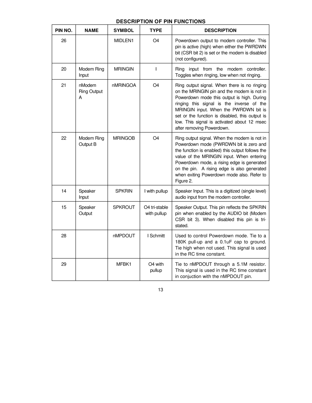
DESCRIPTION OF PIN FUNCTIONS
PIN NO. | NAME | SYMBOL | TYPE | DESCRIPTION |
|
|
|
|
|
26 |
| MIDLEN1 | O4 | Powerdown output to modem controller. This |
|
|
|
| pin is active (high) when either the PWRDWN |
|
|
|
| bit (CSR bit 2) is set or the modem is disabled |
|
|
|
| (not configured). |
|
|
|
|
|
20 | Modem Ring | MRINGIN | I | Ring input from the modem controller. |
| Input |
|
| Toggles when ringing, low when not ringing. |
|
|
|
|
|
21 | nModem | nMRINGOA | O4 | Ring output signal. When there is no ringing |
| Ring Output |
|
| on the MRINGIN pin and the modem is not in |
| A |
|
| Powerdown mode this output is high. During |
|
|
|
| ringing this signal is the inverse of the |
|
|
|
| MRINGIN input. When the PWRDWN bit is |
|
|
|
| set or the function is disabled, this output is |
|
|
|
| low. This signal is activated about 12 msec |
|
|
|
| after removing Powerdown. |
|
|
|
|
|
22 | Modem Ring | MRINGOB | O4 | Ring output signal. When the modem is not in |
| Output B |
|
| Powerdown mode (PWRDWN bit is zero and |
|
|
|
| the function is enabled) this output follows the |
|
|
|
| value of the MRINGIN input. When entering |
|
|
|
| Powerdown mode, a rising edge is generated |
|
|
|
| on the pin. A rising edge is also generated |
|
|
|
| when exiting Powerdown mode also. Refer to |
|
|
|
| Figure 2. |
|
|
|
|
|
14 | Speaker | SPKRIN | I with pullup | Speaker Input. This is a digitized (single level) |
| Input |
|
| audio input from the modem controller. |
|
|
|
|
|
15 | Speaker | SPKROUT | O4 | Speaker Output. This pin reflects the SPKRIN |
| Output |
| with pullup | pin when enabled by the AUDIO bit (Modem |
|
|
|
| CSR bit 3). When disabled this pin is tri- |
|
|
|
| stated. |
|
|
|
|
|
28 |
| nMPDOUT | I Schmitt | Used to control Powerdown mode. Tie to a |
|
|
|
| 180K |
|
|
|
| Tie high when not used. This signal is used |
|
|
|
| in the RC time constant. |
|
|
|
|
|
29 |
| MFBK1 | O4 with | Tie to nMPDOUT through a 5.1M resistor. |
|
|
| pullup | This signal is used in the RC time constant |
|
|
|
| in conjuction with the nMPDOUT pin. |
|
|
|
|
|
|
|
| 13 |
|