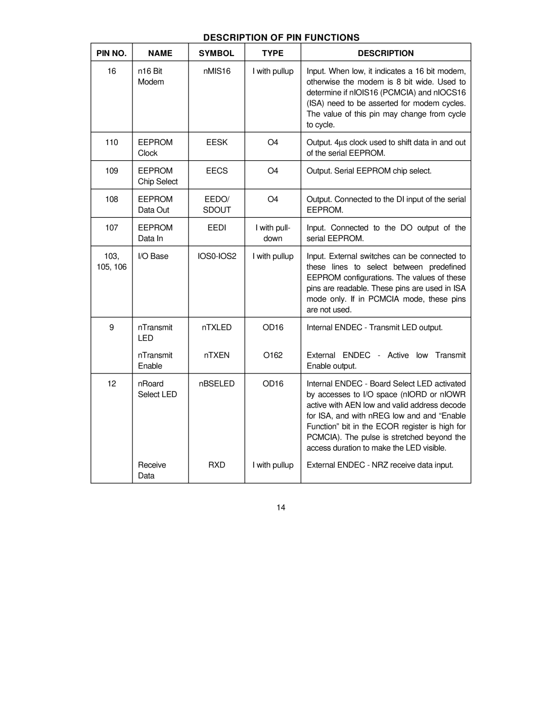
DESCRIPTION OF PIN FUNCTIONS
PIN NO. | NAME | SYMBOL | TYPE | DESCRIPTION |
|
|
|
|
|
16 | n16 Bit | nMIS16 | I with pullup | Input. When low, it indicates a 16 bit modem, |
| Modem |
|
| otherwise the modem is 8 bit wide. Used to |
|
|
|
| determine if nIOIS16 (PCMCIA) and nIOCS16 |
|
|
|
| (ISA) need to be asserted for modem cycles. |
|
|
|
| The value of this pin may change from cycle |
|
|
|
| to cycle. |
|
|
|
|
|
110 | EEPROM | EESK | O4 | Output. 4μs clock used to shift data in and out |
| Clock |
|
| of the serial EEPROM. |
|
|
|
|
|
109 | EEPROM | EECS | O4 | Output. Serial EEPROM chip select. |
| Chip Select |
|
|
|
|
|
|
|
|
108 | EEPROM | EEDO/ | O4 | Output. Connected to the DI input of the serial |
| Data Out | SDOUT |
| EEPROM. |
|
|
|
|
|
107 | EEPROM | EEDI | I with pull- | Input. Connected to the DO output of the |
| Data In |
| down | serial EEPROM. |
|
|
|
|
|
103, | I/O Base |
| I with pullup | Input. External switches can be connected to |
105, 106 |
|
|
| these lines to select between predefined |
|
|
|
| EEPROM configurations. The values of these |
|
|
|
| pins are readable. These pins are used in ISA |
|
|
|
| mode only. If in PCMCIA mode, these pins |
|
|
|
| are not used. |
|
|
|
|
|
9 | nTransmit | nTXLED | OD16 | Internal ENDEC - Transmit LED output. |
| LED |
|
|
|
| nTransmit | nTXEN | O162 | External ENDEC - Active low Transmit |
| Enable |
|
| Enable output. |
|
|
|
|
|
12 | nRoard | nBSELED | OD16 | Internal ENDEC - Board Select LED activated |
| Select LED |
|
| by accesses to I/O space (nIORD or nIOWR |
|
|
|
| active with AEN low and valid address decode |
|
|
|
| for ISA, and with nREG low and and “Enable |
|
|
|
| Function” bit in the ECOR register is high for |
|
|
|
| PCMCIA). The pulse is stretched beyond the |
|
|
|
| access duration to make the LED visible. |
| Receive | RXD | I with pullup | External ENDEC - NRZ receive data input. |
| Data |
|
|
|
|
|
|
|
|
|
|
| 14 |
|