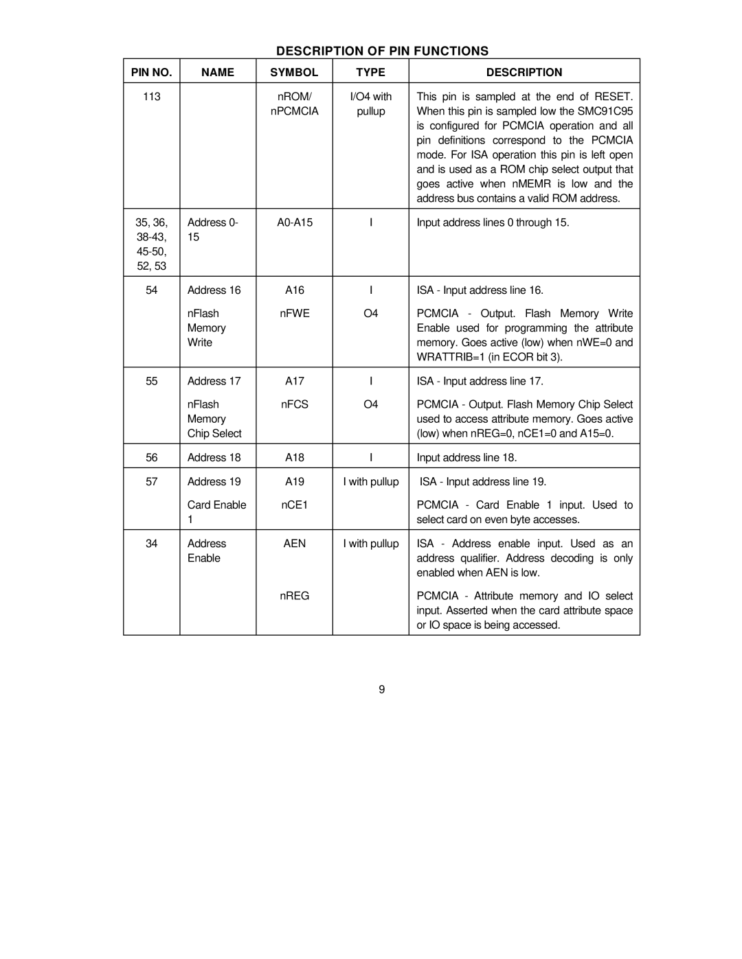
DESCRIPTION OF PIN FUNCTIONS
PIN NO. | NAME | SYMBOL | TYPE | DESCRIPTION |
|
|
|
|
|
113 |
| nROM/ | I/O4 with | This pin is sampled at the end of RESET. |
|
| nPCMCIA | pullup | When this pin is sampled low the SMC91C95 |
|
|
|
| is configured for PCMCIA operation and all |
|
|
|
| pin definitions correspond to the PCMCIA |
|
|
|
| mode. For ISA operation this pin is left open |
|
|
|
| and is used as a ROM chip select output that |
|
|
|
| goes active when nMEMR is low and the |
|
|
|
| address bus contains a valid ROM address. |
|
|
|
|
|
35, 36, | Address 0- | I | Input address lines 0 through 15. | |
15 |
|
|
| |
|
|
|
| |
52, 53 |
|
|
|
|
|
|
|
|
|
54 | Address 16 | A16 | I | ISA - Input address line 16. |
| nFlash | nFWE | O4 | PCMCIA - Output. Flash Memory Write |
| Memory |
|
| Enable used for programming the attribute |
| Write |
|
| memory. Goes active (low) when nWE=0 and |
|
|
|
| WRATTRIB=1 (in ECOR bit 3). |
|
|
|
|
|
55 | Address 17 | A17 | I | ISA - Input address line 17. |
| nFlash | nFCS | O4 | PCMCIA - Output. Flash Memory Chip Select |
| Memory |
|
| used to access attribute memory. Goes active |
| Chip Select |
|
| (low) when nREG=0, nCE1=0 and A15=0. |
|
|
|
|
|
56 | Address 18 | A18 | I | Input address line 18. |
|
|
|
|
|
57 | Address 19 | A19 | I with pullup | ISA - Input address line 19. |
| Card Enable | nCE1 |
| PCMCIA - Card Enable 1 input. Used to |
| 1 |
|
| select card on even byte accesses. |
|
|
|
|
|
34 | Address | AEN | I with pullup | ISA - Address enable input. Used as an |
| Enable |
|
| address qualifier. Address decoding is only |
|
|
|
| enabled when AEN is low. |
|
| nREG |
| PCMCIA - Attribute memory and IO select |
|
|
|
| input. Asserted when the card attribute space |
|
|
|
| or IO space is being accessed. |
|
|
|
|
|
9