BYTE COUNT - Divided by two, it defines the total number of words including the STATUS WORD, the BYTE COUNT WORD, the DATA AREA and the CONTROL BYTE.
The receive byte count always appears as even; the ODDFRM bit of the receive status word indicates if the low byte of the last word is relevant.
The transmit byte count least significant bit will be assumed 0 by the controller regardless of the value written in memory.
DATA AREA - The data area starts at offset 4 of the packet structure and can extend up to 1536 bytes.
The data area contains six bytes of DESTINATION ADDRESS followed by six bytes of SOURCE ADDRESS, followed by a
The 802.3 Frame Length word (Frame Type in Ethernet) is not interpreted by the SMC91C95. It is treated transparently as data both for transmit and receive operations.
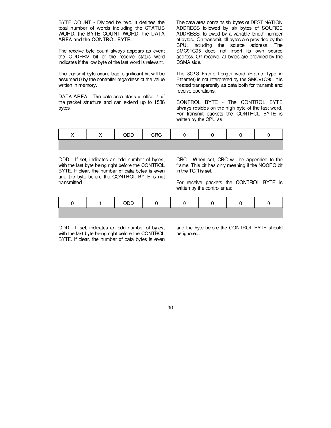
CONTROL BYTE - The CONTROL BYTE always resides on the high byte of the last word. For transmit packets the CONTROL BYTE is written by the CPU as:
X
X
ODD
CRC
0
0
0
0
ODD - If set, indicates an odd number of bytes, with the last byte being right before the CONTROL BYTE. If clear, the number of data bytes is even and the byte before the CONTROL BYTE is not transmitted.
CRC - When set, CRC will be appended to the frame. This bit has only meaning if the NOCRC bit in the TCR is set.
For receive packets the CONTROL BYTE is written by the controller as:
0
1
ODD
0
0
0
0
0
ODD - If set, indicates an odd number of bytes, with the last byte being right before the CONTROL BYTE. If clear, the number of data bytes is even
and the byte before the CONTROL BYTE should be ignored.
30