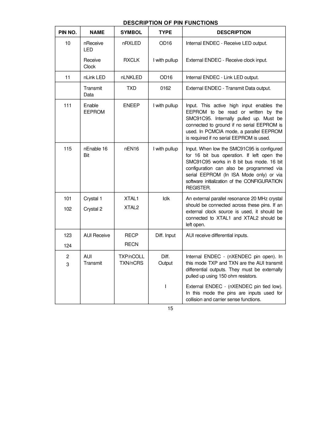
DESCRIPTION OF PIN FUNCTIONS
PIN NO. | NAME | SYMBOL | TYPE | DESCRIPTION |
|
|
|
|
|
10 | nReceive | nRXLED | OD16 | Internal ENDEC - Receive LED output. |
| LED |
|
|
|
| Receive | RXCLK | I with pullup | External ENDEC - Receive clock input. |
| Clock |
|
|
|
|
|
|
|
|
11 | nLink LED | nLNKLED | OD16 | Internal ENDEC - Link LED output. |
|
|
|
|
|
| Transmit | TXD | 0162 | External ENDEC - Transmit Data output. |
| Data |
|
|
|
|
|
|
|
|
111 | Enable | ENEEP | I with pullup | Input. This active high input enables the |
| EEPROM |
|
| EEPROM to be read or written by the |
|
|
|
| SMC91C95. Internally pulled up. Must be |
|
|
|
| connected to ground if no serial EEPROM is |
|
|
|
| used. In PCMCIA mode, a parallel EEPROM |
|
|
|
| is required if no serial EEPROM is used. |
|
|
|
|
|
115 | nEnable 16 | nEN16 | I with pullup | Input. When low the SMC91C95 is configured |
| Bit |
|
| for 16 bit bus operation. If left open the |
|
|
|
| SMC91C95 works in 8 bit bus mode. 16 bit |
|
|
|
| configuration can also be programmed via |
|
|
|
| serial EEPROM (In ISA Mode only) or via |
|
|
|
| software initialization of the CONFIGURATION |
|
|
|
| REGISTER. |
|
|
|
|
|
101 | Crystal 1 | XTAL1 | Iclk | An external parallel resonance 20 MHz crystal |
102 | Crystal 2 | XTAL2 |
| should be connected across these pins. If an |
| external clock source is used, it should be | |||
|
|
|
| |
|
|
|
| connected to XTAL1 and XTAL2 should be |
|
|
|
| left open. |
|
|
|
|
|
123 | AUI Receive | RECP | Diff. Input | AUI receive differential inputs. |
124 |
| RECN |
|
|
|
|
|
|
|
2 | AUI | TXP/nCOLL | Diff. | Internal ENDEC - (nXENDEC pin open). In |
3 | Transmit | TXN/nCRS | Output | this mode TXP and TXN are the AUI transmit |
|
|
|
| differential outputs. They must be externally |
|
|
|
| pulled up using 150 ohm resistors. |
|
|
| I | External ENDEC - (nXENDEC pin tied low). |
|
|
|
| In this mode the pins are inputs used for |
|
|
|
| collision and carrier sense functions. |
|
|
|
|
|
|
|
| 15 |
|