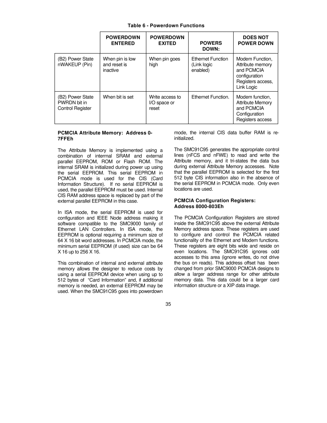
| Table 6 - Powerdown Functions |
| ||
|
|
|
|
|
| POWERDOWN | POWERDOWN | POWERS | DOES NOT |
| ENTERED | EXITED | POWER DOWN | |
|
|
| DOWN: |
|
|
|
|
|
|
(B2) Power State | When pin is low | When pin goes | Ethernet Function | Modem Function, |
nWAKEUP (Pin) | and reset is | high | (Link logic | Attribute memory |
| inactive |
| enabled) | and PCMCIA |
|
|
|
| configuration |
|
|
|
| Registers access, |
|
|
|
| Link Logic |
|
|
|
|
|
(B2) Power State | When bit is set | Write access to | Ethernet Function. | Modem function, |
PWRDN bit in |
| I/O space or |
| Attribute Memory |
Control Register |
| reset |
| and PCMCIA |
|
|
|
| Configuration |
|
|
|
| Registers access |
|
|
|
|
|
PCMCIA Attribute Memory: Address 0- 7FFEh
The Attribute Memory is implemented using a combination of interrnal SRAM and external parallel EEPROM, ROM or Flash ROM. The internal SRAM is initialized during power up using the serial EEPROM. This serial EEPROM in PCMCIA mode is used for the CIS (Card Information Structure). If no serial EEPROM is used, the parallel EEPROM must be used. Internal CIS RAM address space is replaced by part of the external parallel EEPROM in this case.
In ISA mode, the serial EEPROM is used for configuration and IEEE Node address making it software compatible to the SMC9000 family of Ethernet LAN Controllers. In ISA mode, the EEPROM is optional requiring a minimum size of 64 X 16 bit word addresses. In PCMCIA mode, the minimum serial EEPROM (if used) size can be 64 X 16 up to 256 X 16.
This combination of internal and external attribute memory allows the designer to reduce costs by using a serial EEPROM device when using up to 512 bytes of “Card Information” and, if additional memory is needed, an external EEPROM may be used. When the SMC91C95 goes into powerdown
mode, the internal CIS data buffer RAM is re- initialized.
The SMC91C95 generates the appropriate control lines (nFCS and nFWE) to read and write the Attribute memory, and it
PCMCIA Configuration Registers: Address 8000-803Eh
The PCMCIA Configuration Registers are stored inside the SMC91C95 above the external Attribute Memory address space. These registers are used to configure and control the PCMCIA related functionality of the Ethernet and Modem functions. These registers are eight bits wide and reside on even locations. The SMC91C95 ignores odd accesses to this area (ignore writes, do not drive the bus on reads). This address offset has been changed from prior SMC9000 PCMCIA designs to allow a larger address range for other attribute memory data. This data could be a larger card information structure or a XIP data image.
35