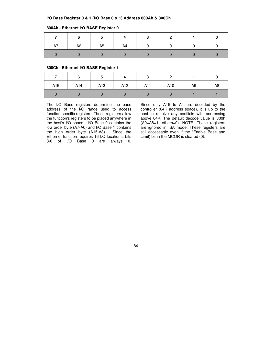
I/O Base Register 0 & 1 (I/O Base 0 & 1) Address 800Ah & 800Ch 800Ah - Ethernet I/O BASE Register 0
7 | 6 | 5 |
| 4 | 3 | 2 | 1 | 0 |
|
|
|
|
|
|
|
|
|
A7 | A6 | A5 |
| A4 | 0 | 0 | 0 | 0 |
|
|
|
|
|
|
|
|
|
0 | 0 | 0 |
| 0 | 0 | 0 | 0 | 0 |
800Ch - Ethernet I/O BASE Register 1 |
|
|
|
|
| |||
|
|
|
|
|
|
|
|
|
7 | 6 | 5 |
| 4 | 3 | 2 | 1 | 0 |
|
|
|
|
|
|
|
|
|
A15 | A14 | A13 |
| A12 | A11 | A10 | A9 | A8 |
|
|
|
|
|
|
|
|
|
0 | 0 | 0 |
| 0 | 0 | 0 | 1 | 1 |
|
|
|
|
|
|
|
|
|
The I/O Base registers determine the base address of the I/O range used to access function specific registers. These registers allow the function's registers to be placed anywhere in the host's I/O space. I/O Base 0 contains the low order byte
Since only A15 to A4 are decoded by the controller (64K address space), it is up to the host to resolve any conflicts with addressing above 64K. The default decode value is 300h (A9=A8=1, others=0). NOTE: These registers are ignored in ISA mode. These registers are still accessable even if the “Enable Base and Limit) bit in the MCOR is cleared (0).
84
