SHBBook Page 2 Wednesday, March 3, 1999 8:03 PM
Installation
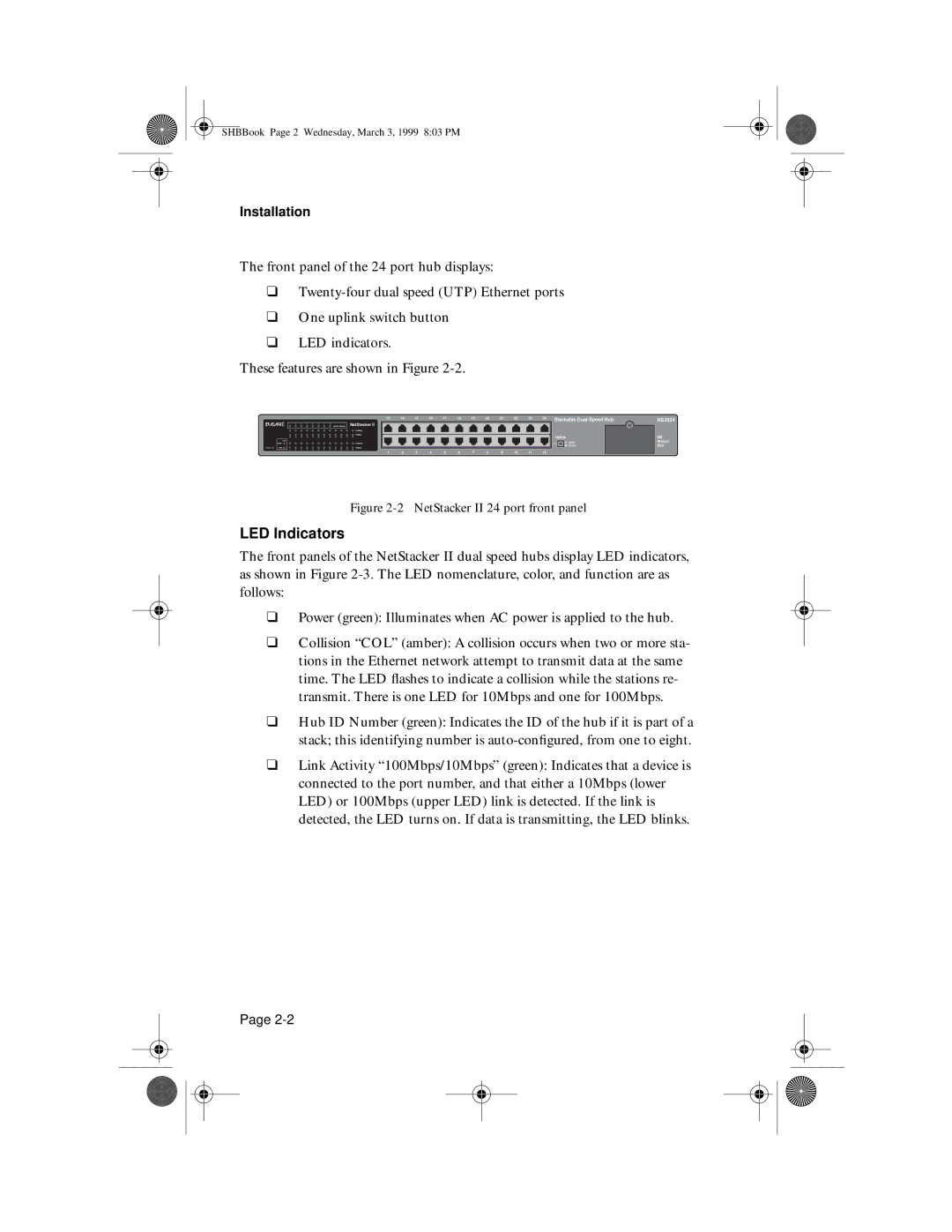
The front panel of the 24 port hub displays:
❑
❑One uplink switch button
❑LED indicators.
These features are shown in Figure
|
| 13 | 14 | 15 | 16 | 17 | 18 | 19 | 20 | 21 | 22 | 23 | 24 | Stackable | |||
| Hub ID Number | NetStacker II |
|
|
|
|
|
|
|
|
|
|
|
|
|
|
|
|
| 100Mbps |
|
|
|
|
|
|
|
|
|
|
|
|
|
|
|
|
| 10Mbps |
|
|
|
|
|
|
|
|
|
|
|
| Uplink | ||
| COL |
|
|
|
|
|
|
|
|
|
|
|
|
|
|
| Uplink |
| 100M | 100Mbps |
|
|
|
|
|
|
|
|
|
|
|
|
|
| |
|
|
|
|
|
|
|
|
|
|
|
|
|
|
|
|
| Normal |
Power | 10M | 10Mbps |
|
|
|
|
|
|
|
|
|
|
|
|
|
|
|
|
| 1 | 2 | 3 | 4 | 5 | 6 | 7 | 8 | 9 | 10 | 11 | 12 |
|
|
| |
NS2024
MII
Module
Slot
Figure 2-2 NetStacker II 24 port front panel
LED Indicators
The front panels of the NetStacker II dual speed hubs display LED indicators, as shown in Figure
❑Power (green): Illuminates when AC power is applied to the hub.
❑Collision “COL” (amber): A collision occurs when two or more sta- tions in the Ethernet network attempt to transmit data at the same time. The LED flashes to indicate a collision while the stations re- transmit. There is one LED for 10Mbps and one for 100Mbps.
❑Hub ID Number (green): Indicates the ID of the hub if it is part of a stack; this identifying number is
❑Link Activity “100Mbps/10Mbps” (green): Indicates that a device is connected to the port number, and that either a 10Mbps (lower LED) or 100Mbps (upper LED) link is detected. If the link is detected, the LED turns on. If data is transmitting, the LED blinks.
Page