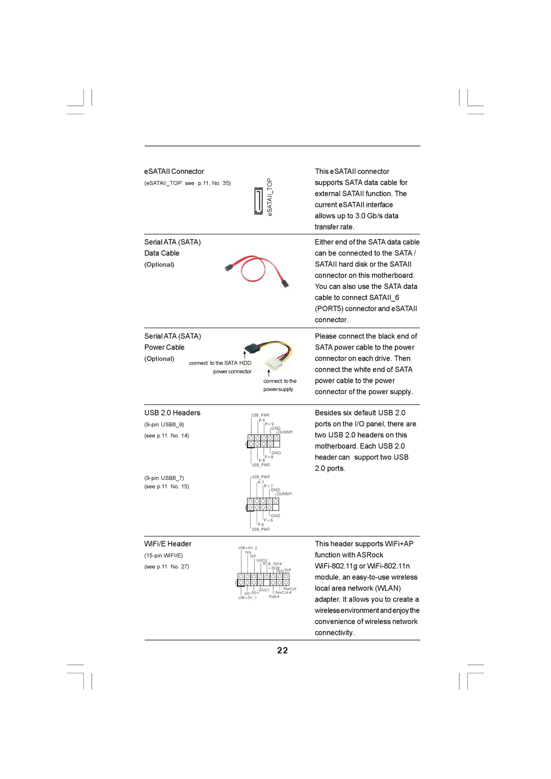
eSATAII Connector
(eSATAII_TOP: see p.11, No. 35)TOP ![]() _eSATAII
_eSATAII
Serial ATA (SATA)
Data Cable
(Optional)
Serial ATA (SATA) |
|
| |
Power Cable |
|
|
|
(Optional) | connect to the SATA HDD |
| |
|
| ||
|
| powerconnector |
|
|
| connect to the | |
|
| powersupply | |
USB 2.0 Headers | USB_PWR |
| |
|
| ||
| P+9 | ||
|
|
| GND |
(see p.11 No. 14) |
| DUMMY | |
|
| ||
|
| 1 |
|
|
|
| GND |
|
| P+8 | |
|
|
| |
|
| USB_PWR |
|
| USB_PWR |
| |
(see p.11 No. 15) |
| ||
P+7 | |||
|
|
| GND |
|
|
| DUMMY |
|
| 1 |
|
|
|
| GND |
|
| P+6 | |
|
|
| |
|
| USB_PWR |
|
WiFi/E Header | USB+5V_2 |
| |
|
|
| |
| TXN |
| |
| TXP |
| |
|
| GND2 |
|
(see p.11 No. 27) | PCIE_RST# | ||
+3SVB | |||
|
|
| RXN RXP |
|
| 1 |
|
|
| GND1 | PexCLK |
|
| D0- D0+ | PexCLK# |
USB+5V_1 PME#
This eSATAII connector supports SATA data cable for external SATAII function. The current eSATAII interface allows up to 3.0 Gb/s data transfer rate.
Either end of the SATA data cable can be connected to the SATA / SATAII hard disk or the SATAII connector on this motherboard. You can also use the SATA data cable to connect SATAII_6 (PORT5) connector and eSATAII connector.
Please connect the black end of SATA power cable to the power connector on each drive. Then connect the white end of SATA power cable to the power connector of the power supply.
Besides six default USB 2.0 ports on the I/O panel, there are two USB 2.0 headers on this motherboard. Each USB 2.0 header can support two USB 2.0 ports.
This header supports WiFi+AP function with ASRock
22