For Windows® XP / XP |
|
|
Click “Audio I/O”, select “Connector Settings” | , choose | |
“Disable front panel jack detection”, and save the change by | ||
clicking “OK”. |
|
|
For Windows® VistaTM / VistaTM |
|
|
Click the | , choose “Disable front | |
panel jack detection”, and save the change by clicking “OK”.
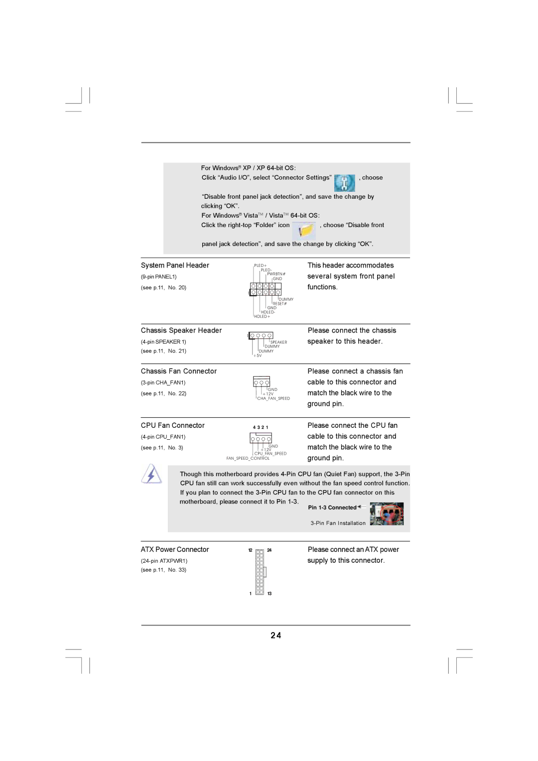
System Panel Header
(see p.11, No. 20)
1
PLED+
PLED-
PWRBTN#
GND
DUMMY RESET#
GND HDLED-
HDLED+
This header accommodates several system front panel functions.
Chassis Speaker Header
1
(see p.11, No. 21)
SPEAKER DUMMY
DUMMY +5V
Please connect the chassis speaker to this header.
Chassis Fan Connector
GND
(see p.11, No. 22)+12V
CHA_FAN_SPEED
Please connect a chassis fan cable to this connector and match the black wire to the ground pin.
CPU Fan Connector | 4 3 2 1 |
| |
(see p.11, No. 3) | +12V |
| GND |
| CPU_FAN_SPEED |
| FAN_SPEED_CONTROL |
Please connect the CPU fan cable to this connector and match the black wire to the ground pin.
Though this motherboard provides
|
|
| Pin |
|
|
| |
|
|
|
|
ATX Power Connector | 12 | 24 | Please connect an ATX power |
|
| supply to this connector. | |
(see p.11, No. 33) |
|
|
|
| 1 | 13 |
|
24