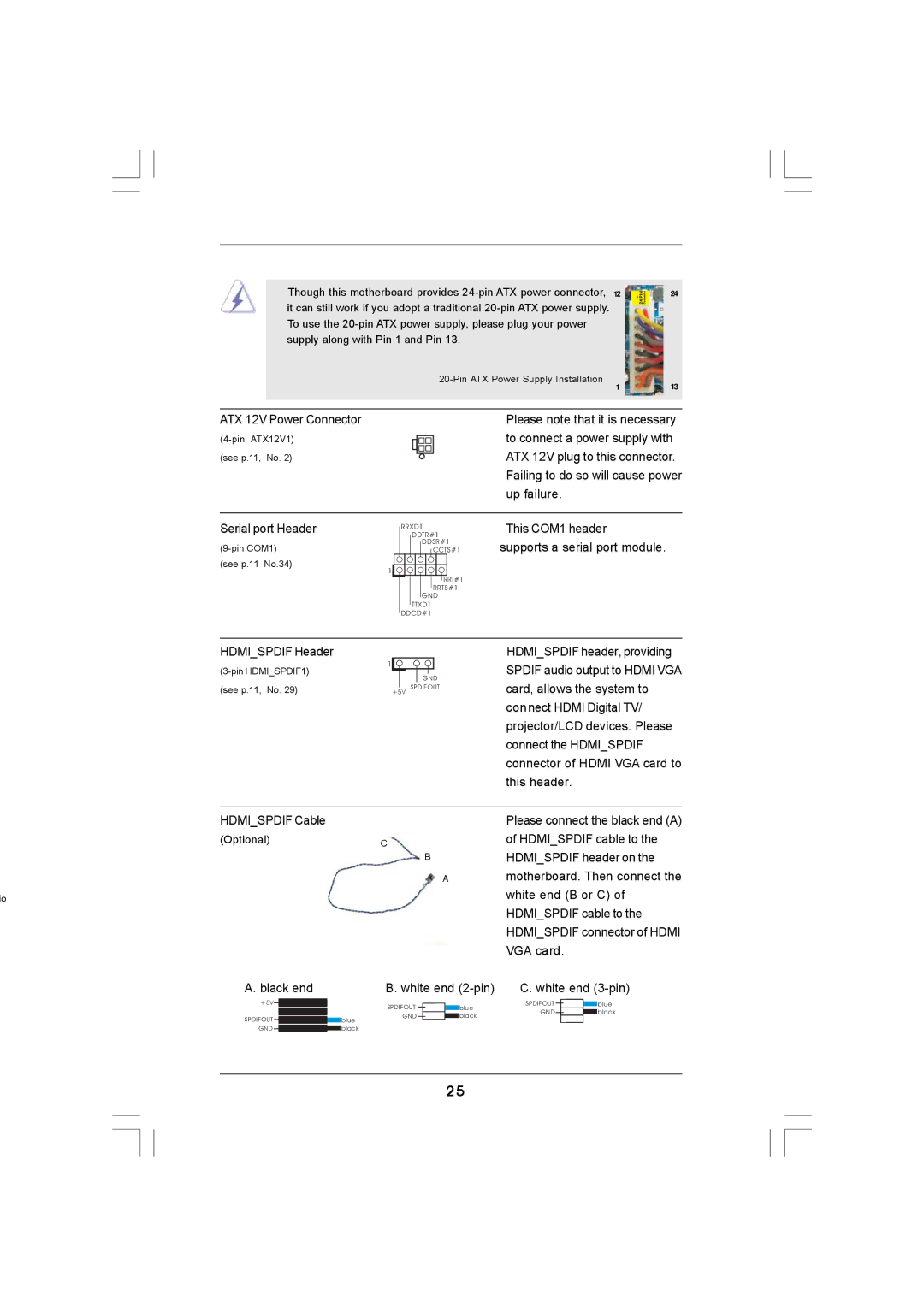
Though this motherboard provides
1
24
13
ATX 12V Power Connector
(see p.11, No. 2)
Please note that it is necessary to connect a power supply with ATX 12V plug to this connector. Failing to do so will cause power up failure.
Serial port Header
(see p.11 No.34)
1
RRXD1
DDTR#1
DDSR#1
CCTS#1
RRI#1
RRTS#1
GND
TTXD1
DDCD#1
This COM1 header
supports a serial port module.
HDMI_SPDIF Header
1 |
|
|
|
|
|
| |
|
|
|
| GND | |||
(see p.11, No. 29) |
| +5V | |||||
|
|
| SPDIFOUT | ||||
HDMI_SPDIF header, providing SPDIF audio output to HDMI VGA card, allows the system to connect HDMI Digital TV/ projector/LCD devices. Please connect the HDMI_SPDIF connector of HDMI VGA card to this header.
HDMI_SPDIF Cable
(Optional)
io
A. black end
+5V |
|
|
|
|
SPDIFOUT |
|
|
| blue |
|
|
| ||
GND |
|
|
| black |
|
|
| ||
|
|
|
|
|
| Please connect the black end (A) |
C | of HDMI_SPDIF cable to the |
BHDMI_SPDIF header on the
Amotherboard. Then connect the white end (B or C) of HDMI_SPDIF cable to the HDMI_SPDIF connector of HDMI VGA card.
B. white end | C. white end | ||||||
SPDIFOUT |
|
|
| blue | SPDIFOUT |
| blue |
GND |
|
|
| black | GND |
| black |
|
|
|
|
|
| ||
25