Motherboard
P5K/EPU
E3691 Second Edition February
Copyright 2008 ASUSTeK COMPUTER INC. All Rights Reserved
Contents
Chapter1 Product introduction
Chapter2 Hardware information
viii
Chapter3 Powering up
Chapter4 BIOS setup
Contents
Chapter5 Software support
Contents
Power menu
Boot menu
Appendix CPU features
Chapter6 ATI CrossFire technology support
A.2.1
A.2.2
Notices
Federal Communications Commission Statement
Canadian Department of Communications Statement
Safety information
Electrical safety
Operation safety
Where to find more information
Chapter 3 Powering up
Chapter 4 BIOS setup
Appendix CPU features
Conventions used in this guide
Typography
Command
Italics
P5K/EPU specifications summary
CPU Chipset System Bus Memory Expansion Slots Storage LAN Audio
P5K/EPU specifications summary
ASUS Stylish Features
ASUS Power Saving Solution
IEEE
P5K/EPU specifications summary
Back Panel I/O Ports Internal I/O Connectors BIOS Features
Manageability Support DVD Contents Form Factor
Page
Product1 introduction
it supports
Chapter summary
ASUS P5K/EPU
1.2 Package contents
1.1 Welcome
1.3 Special features
1.3.1 Product highlights
Intel LGA775 Core 2 Processor Ready
Intel Core2 Duo/ Intel Core2 Extreme CPU support
Gigabit LAN solution
IEEE 1394a support
S/PDIF digital sound ready
High Definition Audio
1.3.2 ASUS AI Lifestyle unique features
ASUS Quiet Thermal Solution
ASUS 3rd Generation 8-Phase Power Design
ASUS EPU
ASUS Q-Connector
ASUS CrashFree BIOS
ASUS Crystal Sound
ASUS EZ DIY
1.3.3 ASUS Intelligent Performance and Overclocking features
ASUS MyLogo3
AI Booster
Precision Tweaker
Hardware2 information
Chapter summary
ASUS P5K/EPU
2.1 Before you proceed
Onboard LED
P5K/EPU Onboard LED
2.2.1 Placement direction
2.2 Motherboard overview
2.2.2 Screw holes
2.2.3 Motherboard layout
24.5cm 9.6in
Intel
PCIEX161
2.2.4 Layout contents
Rear panel connectors
Slots
Page
Internal connectors
ATX power connectors 24-pin EATXPWR, 4-pin EATX12V
Page
2.3 Central Processing Unit CPU
2.3.1 Installing the CPU
To install a CPU 1. Locate the CPU socket on the motherboard
P5K/EPU CPU Socket
If installing a dual-core CPU
to the CHAFAN1 connector to ensure system stability
Close the load plate A, then
push the load lever B until it
2.3.2 Installing the CPU heatsink and fan
To install the CPU heatsink and fan
heatsink and fan assembly in place
P5K/EPU CPU fan connector
2.3.3 Uninstalling the CPU heatsink and fan
the heatsink and fan assembly from
the motherboard
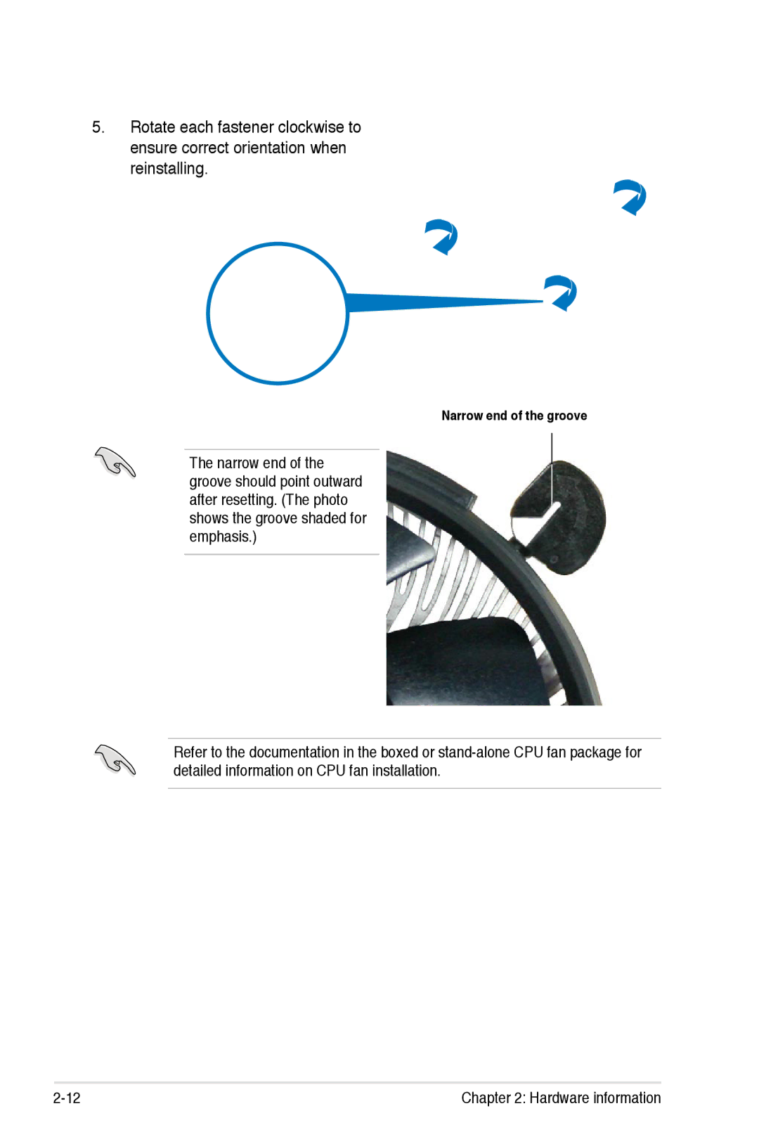
Narrow end of the groove
2-12
Chapter 2 Hardware information
2.4 System memory
2.4.1 Overview
2.4.2 Memory configurations
Mode Single-Channel
64-bit
Sockets
DIMM support
KLED48F-A8KI5-EPA
KHX6400D2LLK2/1GN
HYMP564U64CP8-S5
2-16
Chapter 2 Hardware information
SS - Single-sided / DS - Double-sided DIMM support
HYS72T128020HU-3S-B
HYS64T128020HU-3S-B
M2OAD5G3H3166I1C52
2.4.3 Installing a DIMM
To install a DIMM
2.4.4 Removing a DIMM
1. Unlock a DIMM socket by pressing
2.5.1 Installing an expansion card
2.5.2 Configuring an expansion card
2.5 Expansion slots
2.5.3 Interrupt assignments
IRQ assignments for this motherboard
Priority Standard function
2.5.4 PCI slots
2.5.5 PCI Express x1 slots
2.5.6 PCI Express x16 slots
Universal PCI Express slot max. x4 mode
Primary PCI Express x16 slot
Options for Universal PCI Express operating speed PCI Express slot
2.6 Jumper
1. Clear RTC RAM CLRTC
2.7 Connectors
2.7.1 Rear panel connectors
LAN port LED indications
Audio 2, 4, 6, or 8-channel configuration
2.7.2 Internal connectors
1. Floppy disk drive connector 34-1 pin FLOPPY
2. IDE connector 40-1 pin PRIE IDE
P5K/EPU Floppy disk drive connector
P5K/EPU SATA connectors
right angle side
4. USB connectors 10-1 pin USB 78, USB 9 10, USB 11
5. IEEE 1394a port connector 10-1 pin IE13942
P5K/EPU USB 2.0 connectors
P5K/EPU IEEE 1394a connector
6. CPU, chassis and power fan connectors
4-pin CPUFAN, 3-pin CHAFAN1-2, 3-pin PWRFAN
P5K/EPU Fan connectors
7. Chassis intrusion connector 4-1 pin CHASSIS
8. ATX power connectors 24-pin EATXPWR, 4-pin ATX12V
P5K/EPU Chassis intrusion connector
P5K/EPU ATX power connectors
9. Front panel audio connector 10-1 pin AAFP
P5K/EPU Analog front panel connector
10. Optical drive audio connector 4-pin CD
11. Digital audio connector 4-1 pin SPDIFOUT, for ASUS HDMI VGA card
P5K/EPU Internal audio connector
P5K/EPU Digital audio connector
12. System panel connector 20-8 pin PANEL
System power LED 2-pin PLED
ATX power button/soft-off button 2-pin PWRSW
Reset button 2-pin RESET
ASUS Q-Connector system panel
Powering up
and ways of shutting down the system
Chapter summary
ASUS P5K/EPU
3.1 Starting up for the first time
3.2.1 Using the OS shut down function
3.2.2 Using the dual function power switch
3.2 Turning off the computer
BIOS setup
This chapter tells how to change
the system settings through the BIOS
Setup menus. Detailed descriptions
Chapter summary
4-11
4-16
4-26
4.1 Managing and updating your BIOS
4.1.1 ASUS Update utility
Installing ASUS Update
Updating the BIOS through the Internet
To update the BIOS through the Internet
Updating the BIOS through a BIOS file
Follow the screen instructions to
4.1.2 ASUS EZ Flash 2 utility
Copying the current BIOS
Updating the BIOS file
4.1.3 AFUDOS utility
4. The utility verifies the file and starts updating the BIOS
4.1.4 ASUS CrashFree BIOS 3 utility
Recovering the BIOS from the support DVD
Recovering the BIOS from the USB flash disk
4.2 BIOS setup program
4.2.1 BIOS menu screen
For changing the basic system configuration
For changing the advanced system settings
Power
4.2.6 Configuration fields
4.2.4 Menu items
4.2.5 Sub-menu items
4.2.7 Pop-up window
4.3 Main menu
4.3.1 System Time
4.3.2 System Date Day xx/xx/xxxx
4.3.3 Floppy Diskette A 1.44M, 3.5 in
LBA/Large Mode Auto
PIO Mode Auto
4.3.4 SATA
Type Auto
4.3.5 SATA Configuration
DMA Mode Auto
32Bit Data Transfer Enabled
SATA Configuration Enhanced
Configuration options Enabled Disabled
AMIBIOS
4.3.6 System Information
Processor
System Memory
4.4.1 JumperFree Configuration
4.4 Advanced menu
Ai Overclocking Auto
Loads the optimal settings for the system
CPU Ratio Control Auto
FSB Strap to North Bridge Auto
FSB Frequency
PCIE Frequency Auto
DRAM Command Rate Auto
DRAM Timing Control Auto
DRAM Static Read Control Auto
RAS# to CAS# Delay 5 DRAM Clocks
Transaction Booster Auto
CPU Voltage Auto
CPU PLL Voltage Auto
FSB Termination Voltage Auto
Clock Over-Charging Mode Auto
South Bridge Voltage Auto
Load-Line Calibration Auto
CPU Voltage Reference Auto
4.4.2 USB Configuration
USB Functions Enabled
USB 2.0 Controller Enabled
USB 2.0 Controller Mode HiSpeed
Legacy USB Support Auto
Configuration options Disabled Enabled Auto
Chapter 4 BIOS setup
4-22
4.4.3 CPU Configuration
C1E Support Enabled
CPU TM Function Enabled
Vanderpool Technology Enabled
Max CPUID Value Limit Disabled
IntelR SpeedStep TM Tech. Disabled
North Bridge Chipset Configuration
4.4.4 Chipset
4.4.5 OnBoard Devices Configuration
High Definition Audio Enabled
Onboard 1394 Controller Enabled
Marvell IDE Controller Enabled
4.4.6 PCIPnP
Serial Port1 Address 3F8/IRQ4
Plug And Play O/S NO
4.5 Power menu
4.5.1 Suspend Mode Auto
4.5.2 Repost Video on S3 Resume Disabled
4.5.3 ACPI Version Disabled
4.5.5 APM Configuration
Restore On AC Power Loss Power Off
Power On By RTC Alarm Disabled
Power On By External Modems Disabled
Power On By PS/2 Keyboard Disabled
Power On By PS/2 Mouse Disabled
CPU Temperature xxxºC/xxxºF MB Temperature xxxºC/xxxºF
CPU / Power Fan Speed xxxxRPM or Ignored / N/A
Chassis Q-Fan Control Disabled
Chassis Target Temperature 37C
CPU Fan Profile Optimal
Chassis Fan 1/2 Speed xxxxRPM or Ignored / N/A
4.6 Boot menu
4.6.1 Boot Device Priority
1st ~ xxth Boot Device xxx Drive
4.6.2 Boot Settings Configuration
Quick Boot Enabled
Full Screen Logo Enabled
AddOn ROM Display Mode Force BIOS
Change Supervisor Password
4.6.3 Security
User Access Level Full Access
Change User Password
Clear User Password
Password Check Setup
4.7 Tools menu
4.7.1 ASUS EZ Flash
BIOS SETUP UTILITY
Power
Marvell POST Check LAN Cable Disabled
4.7.2 ASUS Ai Net
Chapter 4 BIOS setup
BIOS SETUP UTILITY
Load Setup Defaults
4.8 Exit menu
Exit & Save Changes
Exit & Discard Changes
Chapter 4 BIOS setup
4-38
Software5 support
5-30
5-41
RAID configurations
Chapter summary
5.1 Installing an operating system
5.2 Support DVD information
5.2.1 Running the support DVD
ASUS InstAll-Drivers Installation Wizard
Intel Chipset Inf Update Program
5.2.2 Drivers menu
Realtek Audio Driver
ASUS InstAll-Installation Wizard for Utilities
5.2.3 Utilities menu
Marvell Yukon VCT Application
ASUS Update
CyberLink PowerBackup
ASUS PC Probe
ASUS AI Suite
5.2.5 Manual menu
5.2.6 ASUS Contact information
5.2.7 Other information
Motherboard Info
Browse this DVD
Chapter 5 Software support
Technical support Form
Filelist
Displays the contents of the support DVD in text format
P5K/EPU
5.3 Software information
5.3.1 ASUS MyLogo3
7. When the logo images appear on the right window pane, select an image to enlarge by clicking on it
Using the Virtual Cable Tester
5.3.2 AI NET2
Installing PC Probe
Using PC Probe
5.3.3 ASUS PC Probe
Launching PC Probe
Preferences
Hardware monitor panels
Adjusting the sensor threshold value
Changing the monitor panels position
Moving the monitor panels
WMI browser
DMI browser
Monitoring sensor alert
PCI browser
Usage
space, and memory usage. Click to display the Usage browser
CPU usage
Configuring PC Probe
Installing AI Suite
Using AI Suite
5.3.4 ASUS AI Suite
Launching AI Suite
Other feature buttons
Click
on right corner of the main window to open the monitor window
Displays the FSB/CPU frequency
5.3.5 ASUS EPU Utility-AI Gear 3+
Energy Saving Status
Click to switch to
Click to reset t h e t i m e t h e calculator starts
Displays the electricity saved since the time was reset
5.3.6 ASUS AI Nap
5.3.7 ASUS Q-Fan
5.3.8 ASUS AI Booster
Using AI Direct Link
5.3.9 ASUS AI Direct Link
folder Disable incoming folder
username and password. Click OK
To connect to another computer
3. The name of the computer found
is listed. Click Open to open its
5-26
Chapter 5 Software support
This chapter tells how to install ATI
ATI CrossFire6 technology support
CrossFire graphics cards to avail of
ATI’s Multi-Video Processing technology
Chapter summary
ASUS P5K/EPU
Overview
Uninstall other graphics card drivers in your system
6.1 Overview
6.1.1 Requirements
6.1.2 Before you begin
6.2 Installing CrossFire graphics cards
To install the graphics cards
ASUS P5K/EPU
5. Connect one end of the external cable to the Master graphics card
7. Connect the loose end to the corresponding port on your monitor
Chapter 6 ATI MVP technology support
6.3.1 Installing the device drivers
Cancel
6.3 Software information
8. Click Finish
6.3.2 Using the Catalyst Control Center
Launching the Catalyst Control Center
On the Windows task bar, click Start ATI Catalyst Control Center
Catalyst Control Center
The Catalyst Control Center Dialog Box
The Catalyst Control Center provides two views
Standard - simple view with wizards for beginners
View
To enable CrossFire 1. Set the view to Advance
Profiles
Preferences
Help
6-12
Chapter 6 ATI MVP technology support
CPU features
Chapter summary
Intel EM64T
Using the Intel EM64T feature
A.1 Intel EM64T
A.2 Enhanced Intel SpeedStep Technology EIST
A.2.1 System requirements
A.2.2 Using the EIST
Using the Hyper-Threading Technology
A.3 Intel Hyper-Threading Technology
Appendix CPU features