CPU Ratio Control [Auto]
Configuration options: [Auto] [Manual]
The following item appears when the CPU Ratio Control item is set to [Manual].
Ratio CMOS Setting [9]
Sets the ratio between CPU Core Clock and the FSB Frequency.
Use the <+> and
FSB Strap to North Bridge [Auto]
FSB Strap will be adjusted automatically by FSB Frequency and DRAM Frequency. Configuration options: [Auto] [200MHz] [266MHz] [333MHz].
The following two items only appear when you set the Ai Overclocking item to [Manual].
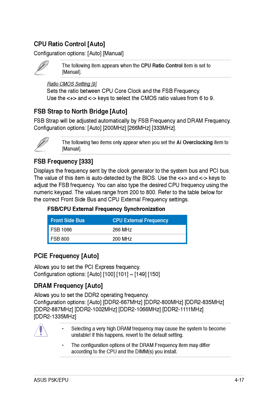
FSB Frequency [333]
Displays the frequency sent by the clock generator to the system bus and PCI bus. The value of this item is
FSB/CPU External Frequency Synchronization
Front Side Bus | CPU External Frequency |
FSB 1066 | 266 MHz |
FSB 800 | 200 MHz |
PCIE Frequency [Auto]
Allows you to set the PCI Express frequency.
Configuration options: [Auto] [100] [101] ~ [149] [150]
DRAM Frequency [Auto]
Allows you to set the DDR2 operating frequency.
Configuration options: [Auto]
•Selecting a very high DRAM frequency may cause the system to become
unstable! If this happens, revert to the default setting.
•The configuration options of the DRAM Frequency item may differ according to the CPU and the DIMM(s) you install.
ASUS P5K/EPU |