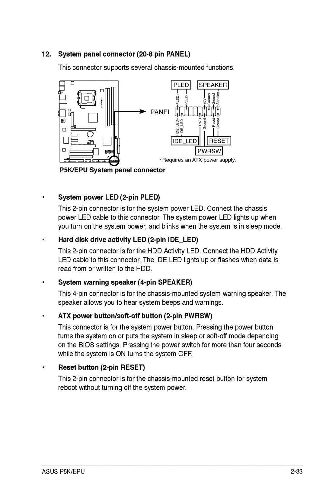
12.System panel connector (20-8 pin PANEL)
This connector supports several chassis-mounted functions.
P5K/EPU
PLED | SPEAKER | |
PLED+ PLED- | +5V | Ground Ground Speaker |
PANEL |
|
|
IDE LED+ IDE LED- | PWR Ground | Reset Ground |
IDE_LED |
| RESET |
PWRSW
*Requires an ATX power supply.
P5K/EPU System panel connector
•System power LED (2-pin PLED)
This
•Hard disk drive activity LED (2-pin IDE_LED)
This
LED cable to this connector. The IDE LED lights up or flashes when data is read from or written to the HDD.
•System warning speaker (4-pin SPEAKER)
This
•ATX power button/soft-off button (2-pin PWRSW)
This connector is for the system power button. Pressing the power button turns the system on or puts the system in sleep or
•Reset button (2-pin RESET)
This
ASUS P5K/EPU |