Using the STK502 Top Module
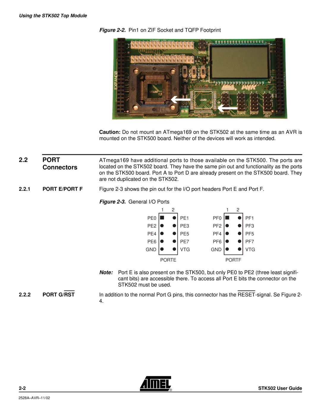
Figure 2-2. Pin1 on ZIF Socket and TQFP Footprint
|
| Caution: Do not mount an ATmega169 on the STK502 at the same time as an AVR is |
|
| mounted on the STK500 board. Neither of the devices will work as intended. |
|
|
|
2.2 | PORT | ATmega169 have additional ports to those available on the STK500. The ports are |
| Connectors | located on the STK502 board. They have the same pin out and functionality as the ports |
|
| on the STK500 board. Port A to Port D are already present on the STK500 board. They |
|
| are not duplicated on the STK502. |
2.2.1PORT E/PORT F Figure
Figure 2-3. General I/O Ports
1 | 2 | 1 | 2 |
PE0
PE2
PE4
PE6
GND
PE1PF0
PE3PF2
PE5PF4
PE7PF6
VTG GND
PF1
PF3
PF5
PF7
VTG
|
|
|
| PORTE | PORTF | ||
|
|
|
| Note: Port E is also present on the STK500, but only PE0 to PE2 (three least signifi- | |||
|
|
|
| cant bits) are accessible there. To access all Port E bits the connector on the | |||
|
|
|
| STK502 must be used. |
|
|
|
|
|
|
|
|
|
| |
2.2.2 | PORT G/RST | In addition to the normal Port G pins, this connector has the | |||||
|
|
|
| 4. |
|
|
|
STK502 User Guide