Technical Specifications
4.1STK502 LCD Bit Mappings
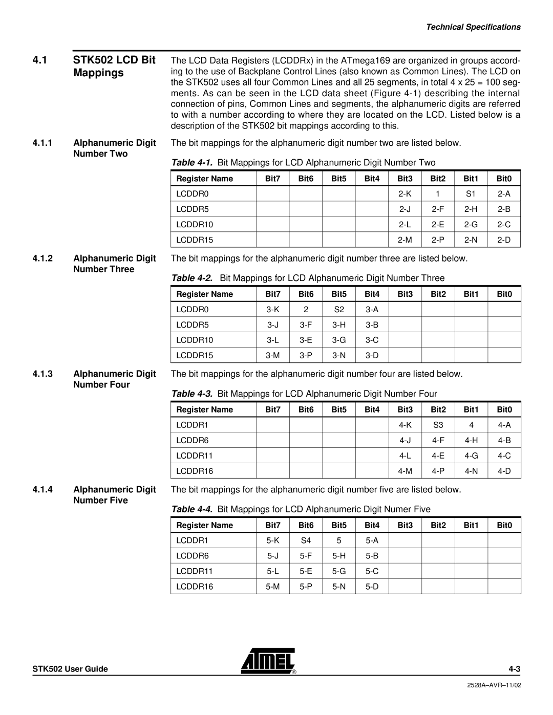
The LCD Data Registers (LCDDRx) in the ATmega169 are organized in groups accord- ing to the use of Backplane Control Lines (also known as Common Lines). The LCD on the STK502 uses all four Common Lines and all 25 segments, in total 4 x 25 = 100 seg- ments. As can be seen in the LCD data sheet (Figure
4.1.1Alphanumeric Digit The bit mappings for the alphanumeric digit number two are listed below.
Number Two
Table
Register Name | Bit7 | Bit6 | Bit5 | Bit4 | Bit3 | Bit2 | Bit1 | Bit0 |
|
|
|
|
|
|
|
|
|
LCDDR0 |
|
|
|
| 1 | S1 | ||
|
|
|
|
|
|
|
|
|
LCDDR5 |
|
|
|
| ||||
|
|
|
|
|
|
|
|
|
LCDDR10 |
|
|
|
| ||||
|
|
|
|
|
|
|
|
|
LCDDR15 |
|
|
|
| ||||
|
|
|
|
|
|
|
|
|
4.1.2Alphanumeric Digit The bit mappings for the alphanumeric digit number three are listed below.
Number Three
Table
Register Name | Bit7 | Bit6 | Bit5 | Bit4 | Bit3 | Bit2 | Bit1 | Bit0 |
|
|
|
|
|
|
|
|
|
LCDDR0 | 2 | S2 |
|
|
|
| ||
|
|
|
|
|
|
|
|
|
LCDDR5 |
|
|
|
| ||||
|
|
|
|
|
|
|
|
|
LCDDR10 |
|
|
|
| ||||
|
|
|
|
|
|
|
|
|
LCDDR15 |
|
|
|
| ||||
|
|
|
|
|
|
|
|
|
4.1.3Alphanumeric Digit The bit mappings for the alphanumeric digit number four are listed below.
Number Four
Table
Register Name | Bit7 | Bit6 | Bit5 | Bit4 | Bit3 | Bit2 | Bit1 | Bit0 |
|
|
|
|
|
|
|
|
|
LCDDR1 |
|
|
|
| S3 | 4 | ||
|
|
|
|
|
|
|
|
|
LCDDR6 |
|
|
|
| ||||
|
|
|
|
|
|
|
|
|
LCDDR11 |
|
|
|
| ||||
|
|
|
|
|
|
|
|
|
LCDDR16 |
|
|
|
| ||||
|
|
|
|
|
|
|
|
|
4.1.4Alphanumeric Digit The bit mappings for the alphanumeric digit number five are listed below.
Number Five
Table 4-4. Bit Mappings for LCD Alphanumeric Digit Numer Five
Register Name | Bit7 | Bit6 | Bit5 | Bit4 | Bit3 | Bit2 | Bit1 | Bit0 |
|
|
|
|
|
|
|
|
|
LCDDR1 | S4 | 5 |
|
|
|
| ||
|
|
|
|
|
|
|
|
|
LCDDR6 |
|
|
|
| ||||
|
|
|
|
|
|
|
|
|
LCDDR11 |
|
|
|
| ||||
|
|
|
|
|
|
|
|
|
LCDDR16 |
|
|
|
| ||||
|
|
|
|
|
|
|
|
|
STK502 User Guide
