|
| Using the STK502 Top Module |
|
|
|
2.5 | LCD Display | STK502 includes a LCD display. It features six |
|
| segments. All in all the display supports 120 segments. The display is designed for 3V |
|
| operating voltage. See the Technical Specifications for more details on the display. |
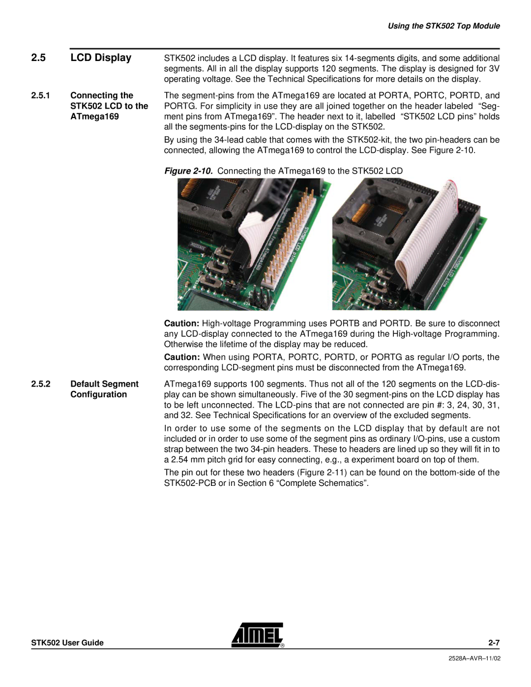
2.5.1Connecting the The
STK502 LCD to the PORTG. For simplicity in use they are all joined together on the header labeled “Seg-
ATmega169ment pins from ATmega169”. The header next to it, labelled “STK502 LCD pins” holds all the
By using the
Figure 2-10. Connecting the ATmega169 to the STK502 LCD
Caution:
Caution: When using PORTA, PORTC, PORTD, or PORTG as regular I/O ports, the corresponding
2.5.2Default Segment ATmega169 supports 100 segments. Thus not all of the 120 segments on the LCD-dis-
Configuration | play can be shown simultaneously. Five of the 30 |
| to be left unconnected. The |
| and 32. See Technical Specifications for an overview of the excluded segments. |
| In order to use some of the segments on the LCD display that by default are not |
| included or in order to use some of the segment pins as ordinary |
| strap between the two |
| a 2.54 mm pitch grid for easy connecting, e.g., a experiment board on top of them. |
| The pin out for these two headers (Figure |
|
|
STK502 User Guide