Using System Designer
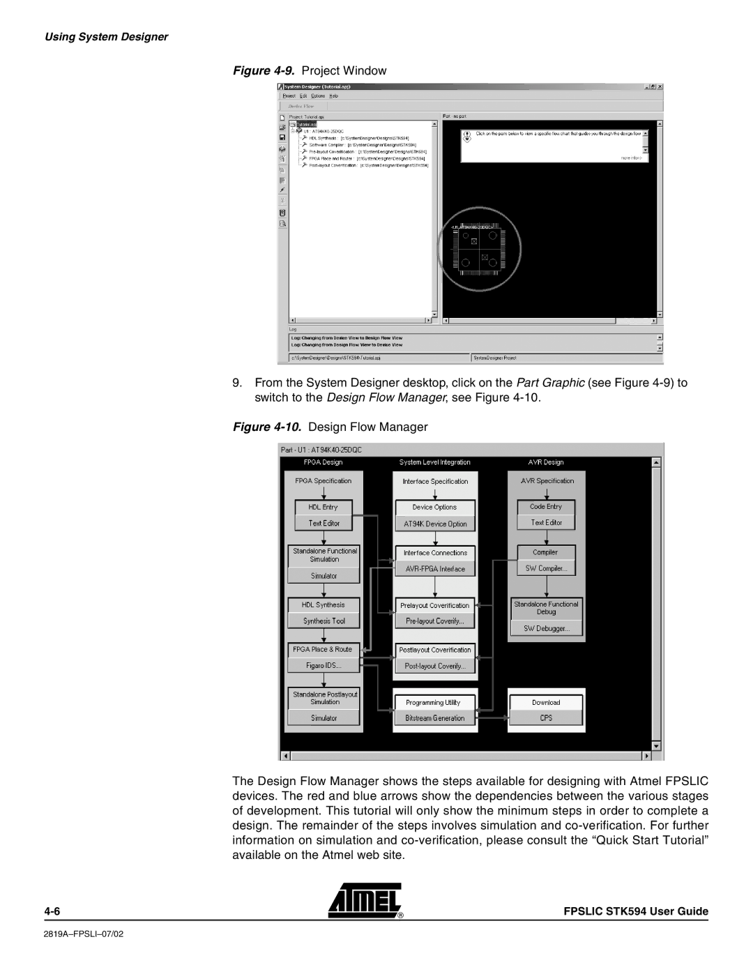
Figure 4-9. Project Window
9.From the System Designer desktop, click on the Part Graphic (see Figure 4-9) to switch to the Design Flow Manager, see Figure 4-10.
Figure 4-10. Design Flow Manager
The Design Flow Manager shows the steps available for designing with Atmel FPSLIC devices. The red and blue arrows show the dependencies between the various stages of development. This tutorial will only show the minimum steps in order to complete a design. The remainder of the steps involves simulation and co-verification. For further information on simulation and co-verification, please consult the “Quick Start Tutorial” available on the Atmel web site.
FPSLIC STK594 User Guide
