Using System Designer
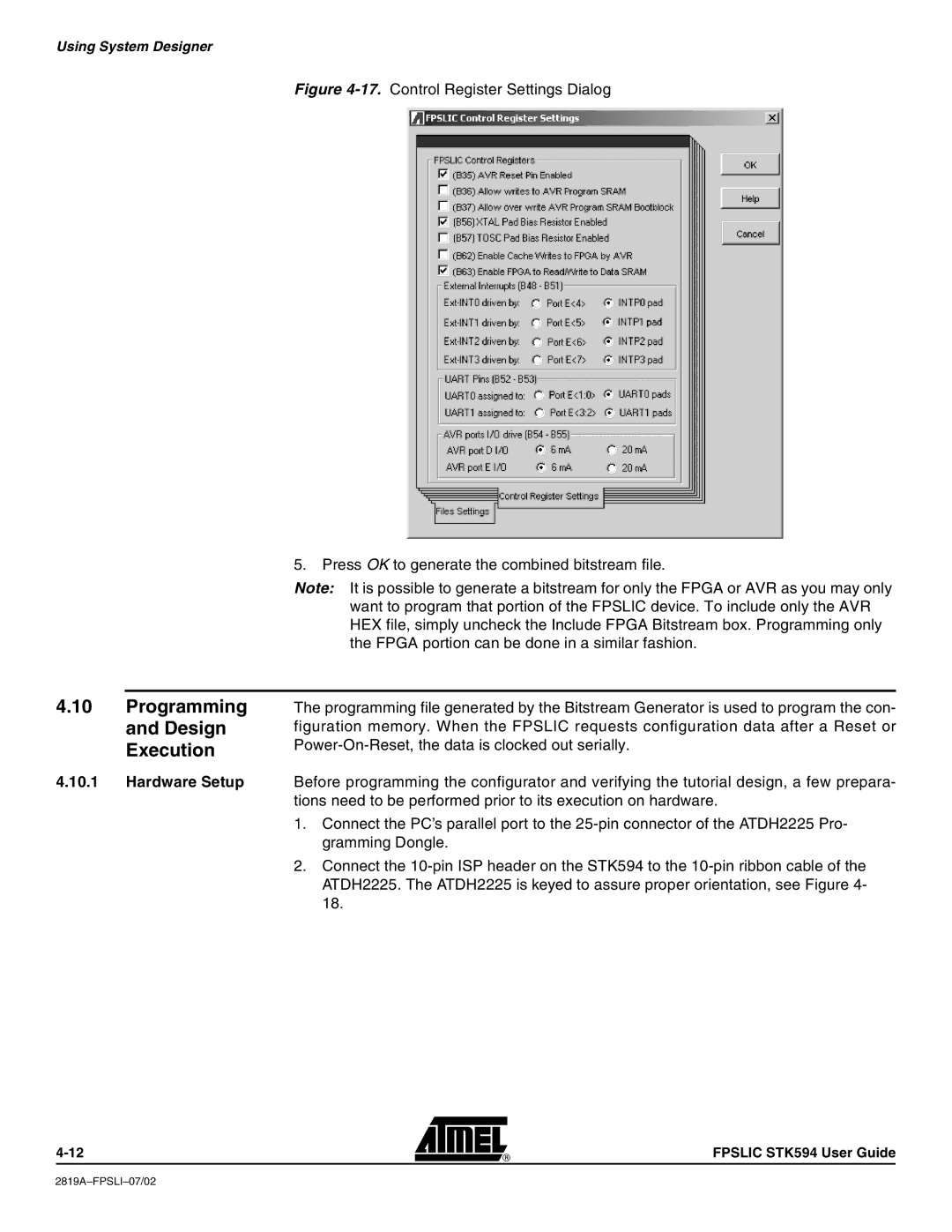
Figure 4-17. Control Register Settings Dialog
5.Press OK to generate the combined bitstream file.
Note: It is possible to generate a bitstream for only the FPGA or AVR as you may only want to program that portion of the FPSLIC device. To include only the AVR HEX file, simply uncheck the Include FPGA Bitstream box. Programming only the FPGA portion can be done in a similar fashion.
4.10Programming and Design Execution
4.10.1Hardware Setup
The programming file generated by the Bitstream Generator is used to program the con- figuration memory. When the FPSLIC requests configuration data after a Reset or
Before programming the configurator and verifying the tutorial design, a few prepara- tions need to be performed prior to its execution on hardware.
1.Connect the PC’s parallel port to the
2.Connect the
FPSLIC STK594 User Guide
