Using System Designer
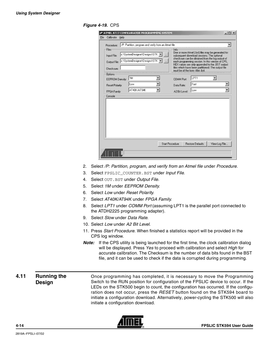
Figure 4-19. CPS
2.Select /P: Partition, program, and verify from an Atmel file under Procedure.
3.Select FPSLIC_COUNTER.BST under Input File.
4.Select OUT.BST under Output File.
5.Select 1M under EEPROM Density.
6.Select Low under Reset Polarity.
7.Select AT40K/AT94K under FPGA Family.
8.Select LPT1 under COMM Port (assuming LPT1 is the parallel port connected to the ATDH2225 programming adapter).
9.Select Slow under Data Rate.
10.Select Low under A2 Bit Level.
11.Press Start Procedure. When finished a statistics report will be provided in the CPS log window.
Note: If the CPS utility is being launched for the first time, the clock calibration dialog will be displayed. Press Yes to proceed with calibration and select High for accurate calibration. The Checksum is the number of data bits found in the BST file, and it can be used to check if the data is corrupted during programming.
4.11Running the Design
Once programming has completed, it is necessary to move the Programming Switch to the RUN position for configuration of the FPSLIC device to occur. If the LEDs on the STK500 begin to count, the configuration has occurred. If the configu- ration does not occur, press the RESET button found on the STK594 board to initiate a configuration download. Alternatively,
FPSLIC STK594 User Guide