Using System Designer
3.Connect the counter's LOAD signal to
4.Select the AVRIoSelects tab on the
5.Select the LOAD signal from the Input Design Ports and select IOSELA0 from the AVRIoSelects.
6.Press Connect.
7.Connect the remaining inputs and outputs as shown in Table
Table
FPGA I/O |
| Select Ports Tab |
|
|
|
LOAD | OSELA0 | AVRIoSelects |
|
|
|
RCO | INTA0 | FPGAInterrupts |
|
|
|
D(7:0) | ADINA(7:0) | DataFromAVR |
|
|
|
aWE | FIOWEA | AVRControls |
|
|
|
CLK | GCLK5 | AVRClocks |
|
|
|
8.Uncheck Generate Template Test Bench File on the bottom
9.Press OK.
4.8FPGA Place and The Figaro Integrated Development System (IDS) is used as the FPGA Place &
Route | Route tool. Figaro takes the |
| thesis tool and partitions, places, and routes the FPGA design. |
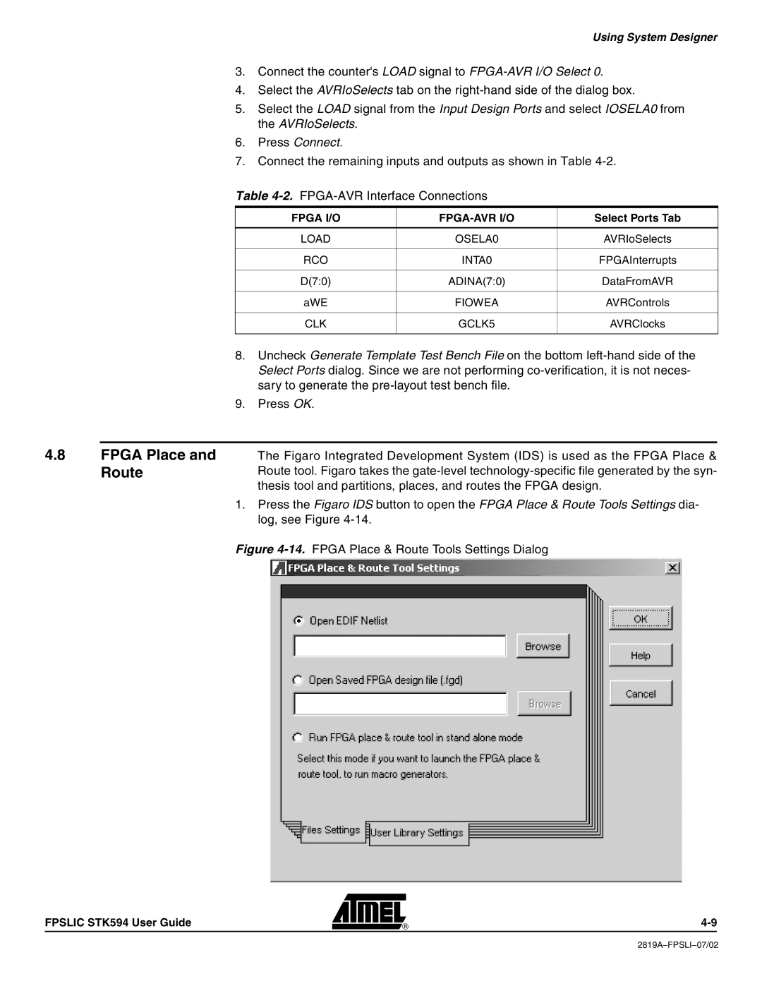
| 1. Press the Figaro IDS button to open the FPGA Place & Route Tools Settings dia- |
| log, see Figure |
| Figure |
FPSLIC STK594 User Guide