Manuals
/
ATTO Technology
/
Home Audio
/
Headphones
ATTO Technology
463-248-202 manual Front Detail, Rear Detail, 4.Rack Mounted Hardware, Power Strip
Models:
463-248-202
1
28
48
48
Download
48 pages
53.09 Kb
25
26
27
28
29
30
31
32
<
>
Troubleshooting
Specs
Install
Connectivity Chart
Warranty
Maintenance
Hardware Configuration
Connecting Speakers
Issue 1, March
Example System Setup
Page 28
Image 28
FRONT DETAIL
1.750 TYPICAL
COMBINATION
PAN HEAD
PILOT POINT
#
10-32(TYPICAL)
REAR DETAIL
POWER STRIP
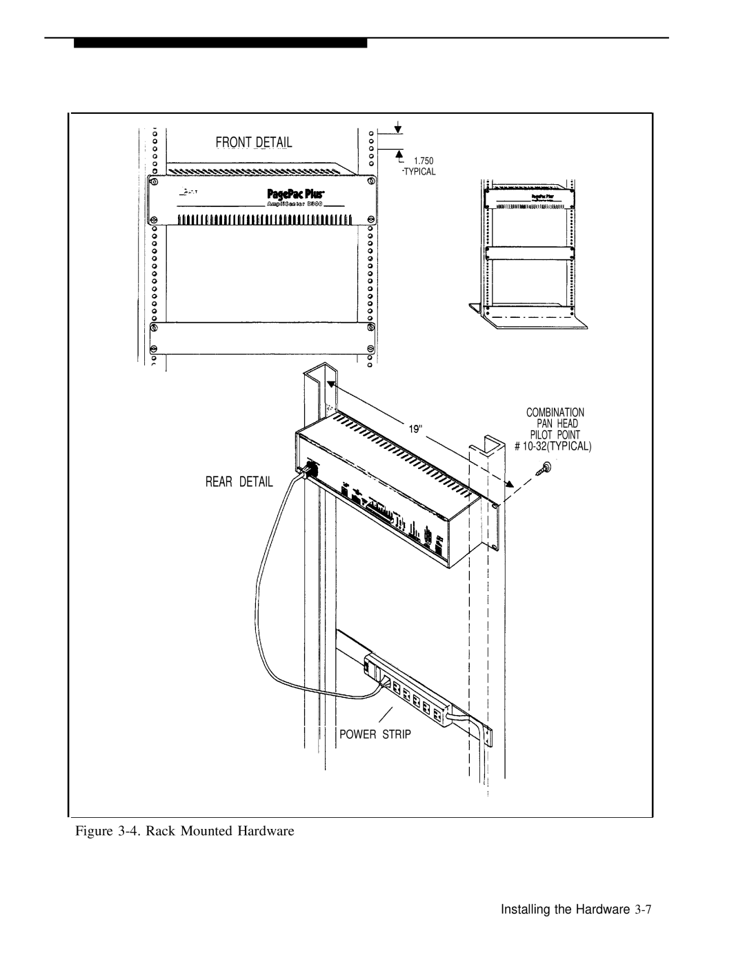
Figure
3-4.
Rack Mounted Hardware
Installing the Hardware
3-7
Page 27
Page 29
Page 28
Image 28
Page 27
Page 29
Contents
Installation and Use
463-248-202 Issue 3/16/93
PagePac Plus AmpliCenter
Warranty
Trademarks
Ordering Information
Support Telephone Numbers
C o n t e n t s
Hardware Configuration
1.Overview
3.Installing the Hardware
4.Maintenance and Customer Support
A.FCC Statement and Warranty Information
B.Feedback Form IN. Index
Overview
T a b l es
Hardware Configuration
Installing
Maintenance and Customer Support
Figures
the Hardware
About This Guide How to Use This Guide
Before You Start Installation Steps
Connectivity Chart Product Safety Labels
How to Comment on this Guide
About This Guide
How to Use This Guide
Before You Start
Installation Steps
Connectivity Chart
Table 1-1.PagePac Plus Connectivity Chart
System
Product Safety Labels
How to Comment on This Guide
Terminology
Reference Materials
Shipping Container Contents
Figure 1-2.AmpliCenter Components
INSTALLATION MANUAL
POWER CORD
Ordering Information
Features and Capabilities
Figure 1-3.PagePac Plus AmpliCenter
Table 1-2.AmpliCenter Specifications
Specifications
Specifications
Hardware Configuration
Power
Controls and Indicators, Terminals and Connectors
Circuit Protection
Circuit Protection
Power
Mounting
Controls and Indicators, Terminals and Connectors
Universal Approvals
3.DC Power, and 70V audio out to Controller
AT&T PagePac Plus Controller PEC
Auxiliary Equipment
AT&T PagePac Plus Zone Expansion Unit PEC
Installing the Hardware
Important Safety Information
Example System Setup
Connecting Speakers
Important Safety Information
Example System Setup
A traditional 70 volt installation
Amplicenter Interface with Controller
Controller System
CONTROLLER
AmpliCenter
3-4 Installing the Hardware
FIRST AMPLICENTER AC POWER CONNECTION PAGING
AC POWER
CONNECTION NEXT APLICENTER NEXT AMPLICENTER
TO NEXT
Mounting PagePac Plus AmpliCenter
Tools Required
SIDE VIEW
Figure 3-3.Wall Mounted Hardware
FRONT DETAIL
REAR DETAIL
Figure 3-4.Rack Mounted Hardware
POWER STRIP
Connecting Speakers
HOME RUN METHOD
SPEAKER-TO-SPEAKERMETHOD
Figure 3-5.Speaker Run Method
Telephone Mode Switch
Telephone System Interface
3-10 Installing the Hardware
Connection to AmpliCenter
Music Source Interface
Music Input
SHIELDED CABLE
FROM EXTERNAL MUSIC SOURCE
Apply AC Power
System Testing
Audio Paging Zones
DTMF digit
Maintenance and Customer Support
Power Failure Operation
Common Problems
Troubleshooting
In Case of Difficulty
Common Problems
Power Failure Operation
Troubleshooting
Table 4-1.Troubleshooting
Green power LED off
Page extension does not
answer
Figure 4-1.AmpliCenter Electrical Block Digram
Electrical Block Diagram
Maintenance and Customer Support
FCC Statement and Warranty Information
FCC Statement Part Radio Frequency Interference
Warranty Information
Limited Warranty and Limitation of Liability
Installation and Maintenance Information
FEEDBACK FORM
Document Installation and Use Guide, Issue
System PagePac Plus AmpliCenter, Release
How are we doing?
Page
Page
Issue 1, March
1993
AT&T
rights