Receiver Controls and Functions (Continued)
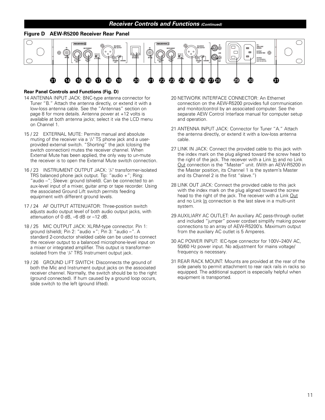
Figure D AEW-R5200 Receiver Rear Panel
IN
ANT. B
INSTRUMENT
ATTN (dB)
EXTERNAL OUTPUT
MUTE (BAL)
BALANCED
MIC OUTPUT
GROUND GROUND LIFT
NETWORK INTERFACE
IN
ANT. A
INSTRUMENT
ATTN (dB)
EXTERNAL OUTPUT
MUTE (BAL)
BALANCED
MIC OUTPUT
GROUND GROUND
LIFT
IN
LINK
OUT
AC˜
OUTPUT 5A/500W MAX
WARNING:
THIS APPARATUS MUST BE EARTHED.
31 | 14 | 15 | 16 | 17 | 18 | 19 | 20 | 21 | 22 | 23 | 24 | 25 | 26 | 27 28 | 29 | 30 | 31 |
Rear Panel Controls and Functions (Fig. D)
14 ANTENNA INPUT JACK:
15 / 22 EXTERNAL MUTE: Permits manual and absolute muting of the receiver via a 1/4" TS phone jack and a user- provided external switch. “Shorting” the jack (closing the switch connection) mutes the receiver channel. When External Mute has been applied, the only way to
16 / 23 INSTRUMENT OUTPUT JACK: 1/4"
17 / 24 AF OUTPUT ATTENUATOR:
18 / 25 MIC OUTPUT JACK:
19 / 26 GROUND LIFT SWITCH: Disconnects the ground of both the Mic and Instrument output jacks on the associated receiver channel. Normally, the switch should be to the right (ground connected). If hum caused by a ground loop occurs, slide switch to the left (ground lifted).
20 NETWORK INTERFACE CONNECTOR: An Ethernet connection on the
21 ANTENNA INPUT JACK: Connector for Tuner “A.” Attach the antenna directly, or extend it with a
27 LINK IN JACK: Connect the provided cable to this jack with the index mark on the plug aligned toward the screw head to the right of the jack. The receiver with a Link In and no Link Out connection is the “Master” unit. (With an
28 LINK OUT JACK: Connect the provided cable to this jack with the index mark on the plug aligned toward the screw head to the right of the jack. The receiver with a Link Out and no Link In connection is the last slave in a
29 AUXILIARY AC OUTLET: An auxiliary AC
30 AC POWER INPUT:
31 REAR RACK MOUNT: Mounts are provided at the rear of the side panels to permit attachment to rear rack rails in racks so equipped. The additional support is especially helpful when equipment is transported.
11