Receiver Controls and Functions (Continued)
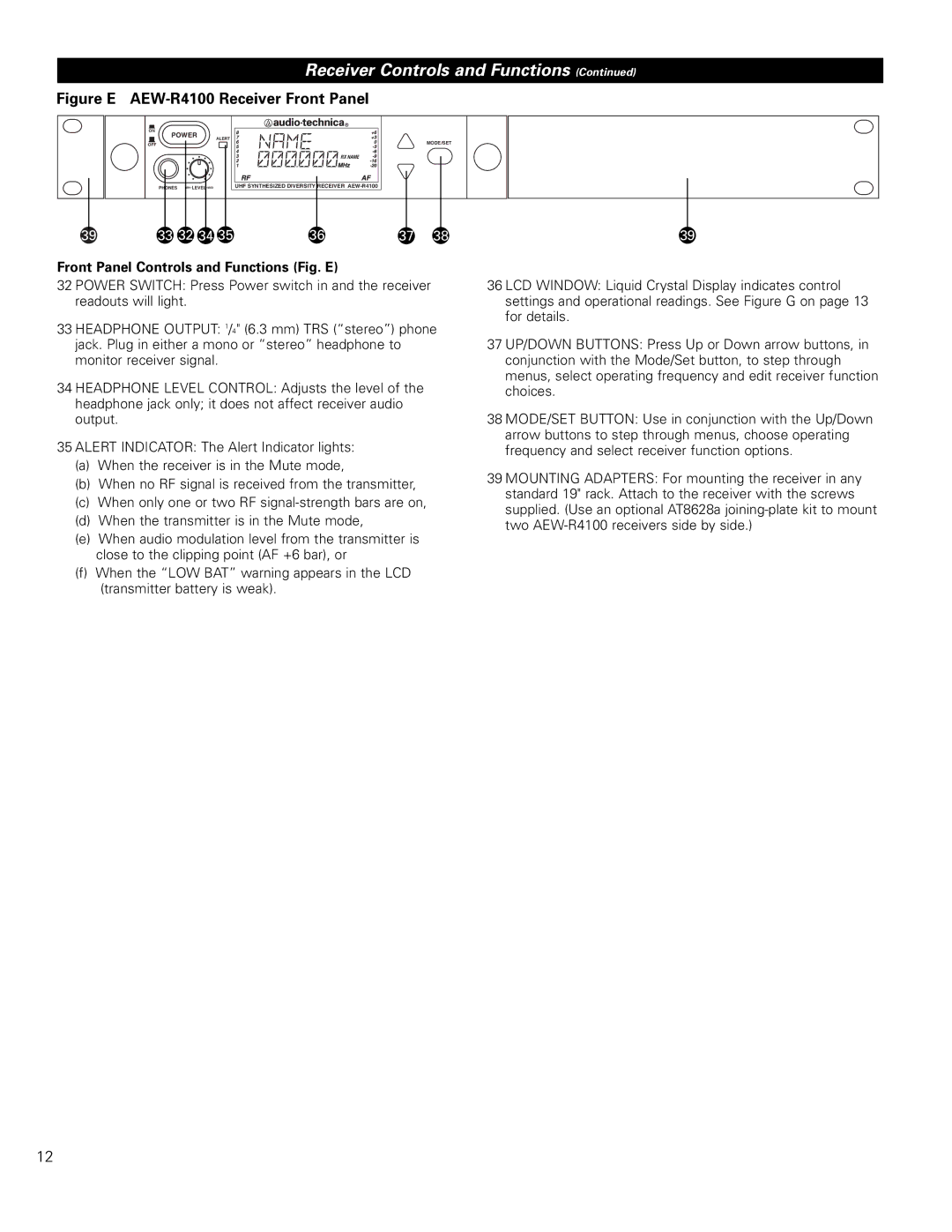
Figure E AEW-R4100 Receiver Front Panel
ON
![]() POWER
POWER![]()
ALERT
OFF
![]() RX NAME
RX NAME
MODE/SET
PHONES
UHF SYNTHESIZED DIVERSITY RECEIVER
39 | 33 32 34 35 | 36 | 37 | 38 | 39 |
Front Panel Controls and Functions (Fig. E)
32 POWER SWITCH: Press Power switch in and the receiver readouts will light.
33 HEADPHONE OUTPUT: 1/4" (6.3 mm) TRS (“stereo”) phone jack. Plug in either a mono or “stereo” headphone to monitor receiver signal.
34 HEADPHONE LEVEL CONTROL: Adjusts the level of the headphone jack only; it does not affect receiver audio output.
35 ALERT INDICATOR: The Alert Indicator lights:
(a)When the receiver is in the Mute mode,
(b)When no RF signal is received from the transmitter,
(c)When only one or two RF
(d)When the transmitter is in the Mute mode,
(e)When audio modulation level from the transmitter is close to the clipping point (AF +6 bar), or
(f)When the “LOW BAT” warning appears in the LCD (transmitter battery is weak).
36 LCD WINDOW: Liquid Crystal Display indicates control settings and operational readings. See Figure G on page 13 for details.
37 UP/DOWN BUTTONS: Press Up or Down arrow buttons, in conjunction with the Mode/Set button, to step through menus, select operating frequency and edit receiver function choices.
38 MODE/SET BUTTON: Use in conjunction with the Up/Down arrow buttons to step through menus, choose operating frequency and select receiver function options.
39 MOUNTING ADAPTERS: For mounting the receiver in any standard 19" rack. Attach to the receiver with the screws supplied. (Use an optional AT8628a
12