Receiver Installation (Continued)
Ethernet connections
computer connected to the Master receiver.
Multiple
Other than being able to “see” the “RF” and “AF” levels, all functions of all receivers in a linked system can be monitored and controlled from the computer connected to the Master receiver.
Details of the computer setup and operation will be found in a separate AEW Control Interface manual provided with
Receiver Controls and Functions
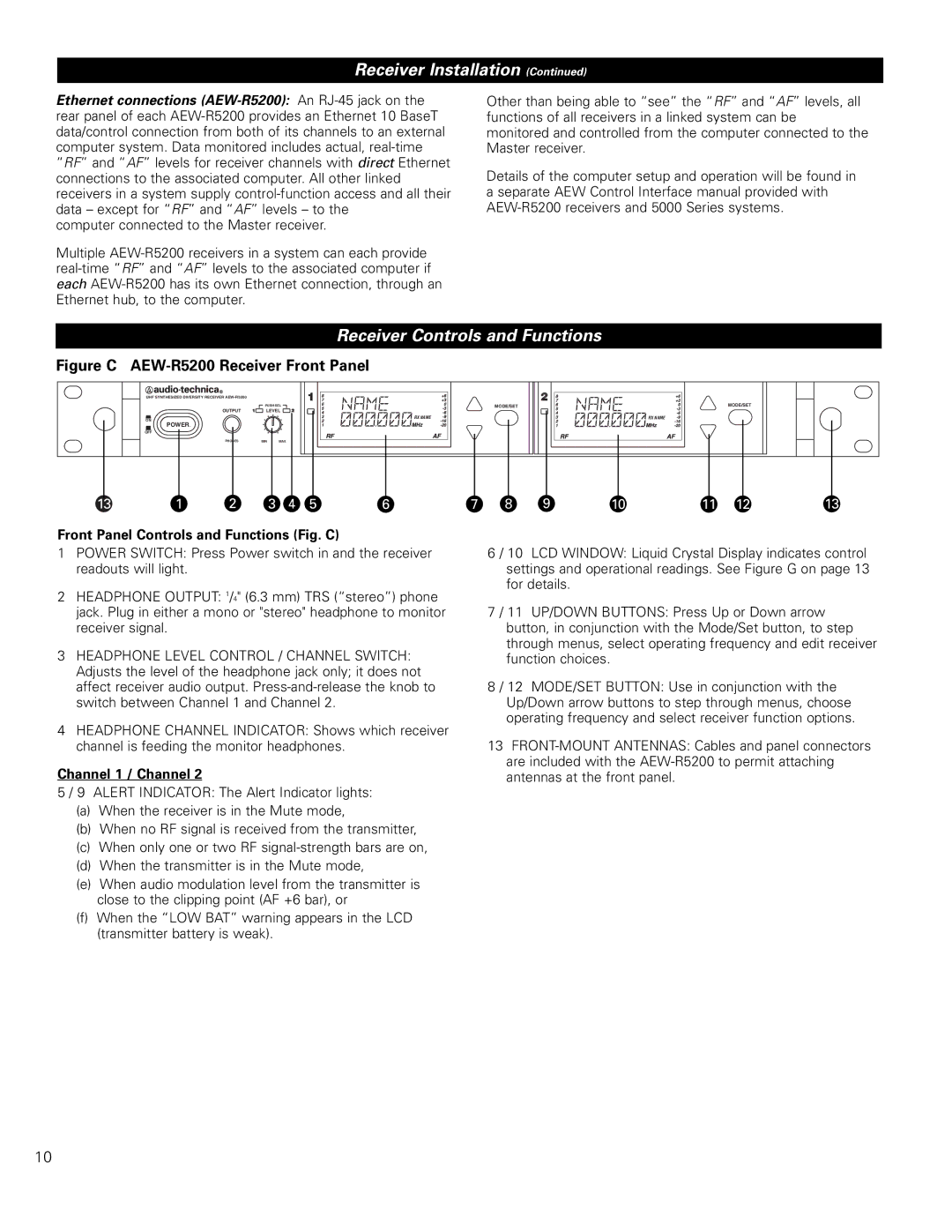
Figure C AEW-R5200 Receiver Front Panel
UHF SYNTHESIZED DIVERSITY RECEIVER
PUSH SEL ![]()
OUTPUT | LEVEL |
ON
POWER
OFF
![]() RX NAME
RX NAME
MODE/SET
![]() RX NAME
RX NAME
MODE/SET
PHONES | MIN | MAX |
13 | 1 | 2 | 3 | 4 | 5 | 6 | 7 | 8 | 9 | 10 | 11 | 12 | 13 |
Front Panel Controls and Functions (Fig. C)
1POWER SWITCH: Press Power switch in and the receiver readouts will light.
2HEADPHONE OUTPUT: 1/4" (6.3 mm) TRS (“stereo”) phone jack. Plug in either a mono or "stereo" headphone to monitor receiver signal.
3HEADPHONE LEVEL CONTROL / CHANNEL SWITCH: Adjusts the level of the headphone jack only; it does not affect receiver audio output.
4HEADPHONE CHANNEL INDICATOR: Shows which receiver channel is feeding the monitor headphones.
Channel 1 / Channel 2
5 / 9 ALERT INDICATOR: The Alert Indicator lights:
(a)When the receiver is in the Mute mode,
(b)When no RF signal is received from the transmitter,
(c)When only one or two RF
(d)When the transmitter is in the Mute mode,
(e)When audio modulation level from the transmitter is close to the clipping point (AF +6 bar), or
(f)When the “LOW BAT” warning appears in the LCD (transmitter battery is weak).
6 / 10 LCD WINDOW: Liquid Crystal Display indicates control settings and operational readings. See Figure G on page 13 for details.
7 / 11 UP/DOWN BUTTONS: Press Up or Down arrow button, in conjunction with the Mode/Set button, to step through menus, select operating frequency and edit receiver function choices.
8 / 12 MODE/SET BUTTON: Use in conjunction with the Up/Down arrow buttons to step through menus, choose operating frequency and select receiver function options.
13
10