9

Receiver Installation (Continued)
Front-mount Antennas
AEW-R4100: Provision has been made to move the antenna
jacks from the rear to the front of the receiver. However,
because this involves opening the receiver case and exposing
AC power circuitry, instructions are not included in this manual.
A qualified service technician must perform this modification.
AEW-R5200: BNC-to-BNC connectors and jumper cables are
included with the unit to permit mounting antennas on the front
panel.
• BNC-BNC through-panel connectors: Remove the nut and
lock-washer from each connector. Install the connectors
from the front into the two panel holes. Note that the flat
on the threaded section must be aligned with the flat in
each panel hole. Secure each connector from the back with
its lock-washer and nut, tightening the nut firmly.
• BNC-BNC cable jumpers: Connect the jumpers to the rear
antenna jacks first; then attach them to the BNC connectors
on the front panel. Make certain the bayonet twist-rings are
fully latched on the connectors at both ends.
Headphone Jack
A headphone jack on the front panel provides monitoring of the
receiver’s output. The 1/4" TRS jack is intended for use with
stereo headphones. The Phones Level control affects the
headphone jack only. Note: On an operating unit, be careful
not to press the Power switch accidentally when inserting a
headphone jack or adjusting the headphone level. In addition
to interrupting receiver operation, even a momentary loss of
power to a single unit within a linked multi-channel system will
cause the loss of linking connection to the affected receiver and
all those “downstream” from it.
AEW-R5200: Press and release the Phones Level control knob
to switch headphone monitoring from Channel 1 to Channel 2
and back again. Small, lighted indicators just above the knob
show which receiver channel is being monitored.
Power Connections
The switching power supply is designed to operate properly
from any AC power source 100–240V, 50/60 Hz without user
adjustment. Simply connect the receiver to a standard AC
power outlet, using only an IEC-type input cordset approved
for the country of use. Power to the unit is controlled by the
front-panel Power switch.
AEW-R5200: An auxiliary AC “jumper” (pass-through) outlet is
provided on the rear panel, and a ”jumper” power cordset is
included, to simplify power connections by “daisy-chaining”
an array of AEW-R5200’s. Maximum output from the auxiliary
outlet is 5 Amperes, which will easily handle a full complement
of AEW-R5200 units.
“Link” Connections
Artist Elite Series multi-channel systems can comprise all
AEW-R4100, all AEW-R5200, or combinations of AEW-R4100
and AEW-R5200 receivers. The exclusive IntelliScanchannel
assignment system provides easy, automatic scanning of the
RF spectrum and assignment of usable, compatible frequencies
to all linked AEW receiver channels.
Both AEW receiver models can be interconnected using Link
In/Out jacks and included link cables. In addition, the
AEW-R5200 offers a built-in Ethernet 10 BaseT connection,
with interface software provided on CD-ROM. See the separate
AEW Control Interface manual provided with AEW-R5200
receivers and 5000 Series systems.
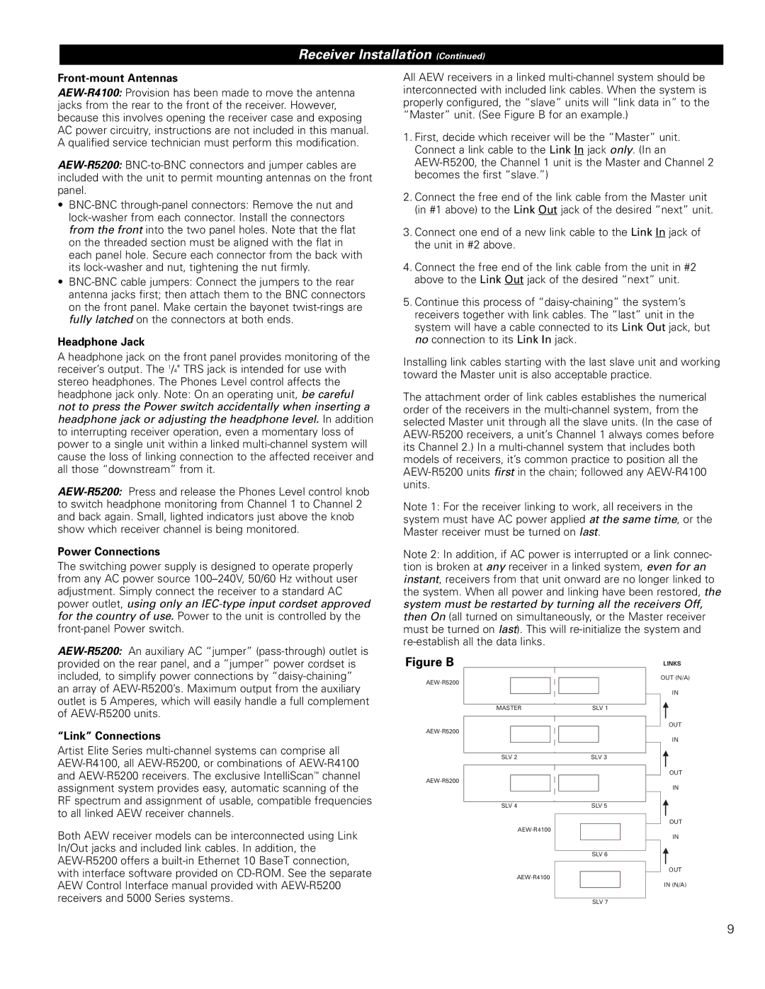
All AEW receivers in a linked multi-channel system should be
interconnected with included link cables. When the system is
properly configured, the “slave” units will “link data in” to the
“Master” unit. (See Figure B for an example.)
1.First, decide which receiver will be the “Master” unit.
Connect a link cable to the Link In jack only. (In an
AEW-R5200, the Channel 1 unit is the Master and Channel 2
becomes the first “slave.”)
2.Connect the free end of the link cable from the Master unit
(in #1 above) to the Link Out jack of the desired “next” unit.
3.Connect one end of a new link cable to the Link In jack of
the unit in #2 above.
4.Connect the free end of the link cable from the unit in #2
above to the Link Out jack of the desired “next” unit.
5.Continue this process of “daisy-chaining” the system’s
receivers together with link cables. The “last” unit in the
system will have a cable connected to its Link Out jack, but
no connection to its Link In jack.
Installing link cables starting with the last slave unit and working
toward the Master unit is also acceptable practice.
The attachment order of link cables establishes the numerical
order of the receivers in the multi-channel system, from the
selected Master unit through all the slave units. (In the case of
AEW-R5200 receivers, a unit’s Channel 1 always comes before
its Channel 2.) In a multi-channel system that includes both
models of receivers, it’s common practice to position all the
AEW-R5200 units first in the chain; followed any AEW-R4100
units.
Note 1: For the receiver linking to work, all receivers in the
system must have AC power applied at the same time, or the
Master receiver must be turned on last.
Note 2: In addition, if AC power is interrupted or a link connec-
tion is broken at any receiver in a linked system, even for an
instant, receivers from that unit onward are no longer linked to
the system. When all power and linking have been restored, the
system must be restarted by turning all the receivers Off,
then On (all turned on simultaneously, or the Master receiver
must be turned on last). This will re-initialize the system and
re-establish all the data links.

Figure B

AEW-R5200
AEW-R5200
AEW-R5200
AEW-R4100
AEW-R4100
MASTER SLV 1
SLV 2 SLV 3
SLV 4 SLV 5
SLV 6
SLV 7
OUT
IN
OUT
IN
OUT
IN
OUT
IN (N/A)
OUT (N/A)
IN
LINKS