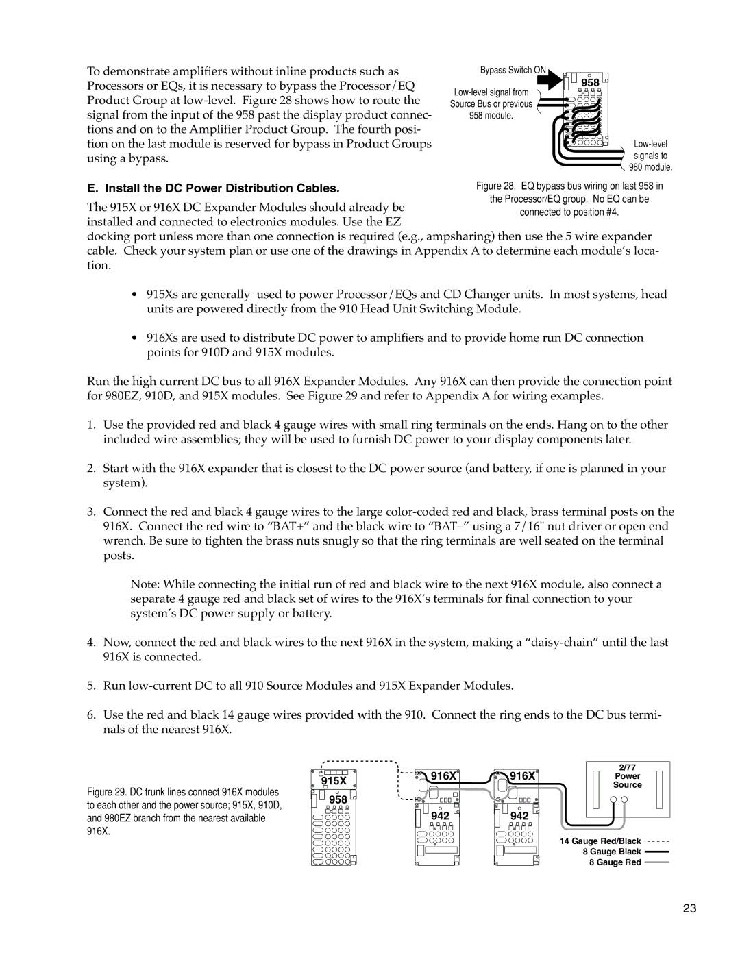
To demonstrate amplifiers without inline products such as Processors or EQs, it is necessary to bypass the Processor/EQ Product Group at
E. Install the DC Power Distribution Cables.
Bypass Switch ON
![]()
![]() 958
958
The 915X or 916X DC Expander Modules should already be installed and connected to electronics modules. Use the EZ
docking port unless more than one connection is required (e.g., ampsharing) then use the 5 wire expander cable. Check your system plan or use one of the drawings in Appendix A to determine each module’s loca- tion.
•915Xs are generally used to power Processor/EQs and CD Changer units. In most systems, head units are powered directly from the 910 Head Unit Switching Module.
•916Xs are used to distribute DC power to amplifiers and to provide home run DC connection points for 910D and 915X modules.
Run the high current DC bus to all 916X Expander Modules. Any 916X can then provide the connection point for 980EZ, 910D, and 915X modules. See Figure 29 and refer to Appendix A for wiring examples.
1.Use the provided red and black 4 gauge wires with small ring terminals on the ends. Hang on to the other included wire assemblies; they will be used to furnish DC power to your display components later.
2.Start with the 916X expander that is closest to the DC power source (and battery, if one is planned in your system).
3.Connect the red and black 4 gauge wires to the large
Note: While connecting the initial run of red and black wire to the next 916X module, also connect a separate 4 gauge red and black set of wires to the 916X’s terminals for final connection to your system’s DC power supply or battery.
4.Now, connect the red and black wires to the next 916X in the system, making a
5.Run
6.Use the red and black 14 gauge wires provided with the 910. Connect the ring ends to the DC bus termi- nals of the nearest 916X.
Figure 29. DC trunk lines connect 916X modules to each other and the power source; 915X, 910D, and 980EZ branch from the nearest available 916X.
915X
![]()
![]() 958
958
916X
![]()
![]()
![]() 942
942 ![]()
916X | 2/77 |
Power | |
| Source |
![]()
![]()
![]() 942
942 ![]()
14 Gauge Red/Black
8 Gauge Black
8 Gauge Red
23