Remote System Reset
There is a “System Reset” button on the 980 that enables the user to reset the system in the unlikely event that the system “hangs up.” Pressing this button will
•Connect a SPST switch between the “Reset” and “COM” pins on the “Remotes” terminal block located on the 980 (see Figure 38).
•Your system can now be Reset using this remote switch.
TESTING NETWORK FUNCTION
A. After installation is complete, all the system’s components need to be tested. Apply power to the system and observe the following signs of normal operation:
•The green SilenTouch™ LED is lit on the 980.
•The green POWER or heartbeat LEDs on the switching modules and the 980 are slowly blinking.
•The red 980 LOW VOLTAGE LED is not lit, or very dim.
Note: If the LOW VOLTAGE LED is lit, your system will not function. The system shuts down if the DC power source (usually the battery) is providing 9 volts DC or less. Check the output voltage of your battery and power supply and contact the factory.
•The red TheftAlert™ LED on the 980 is not lit.
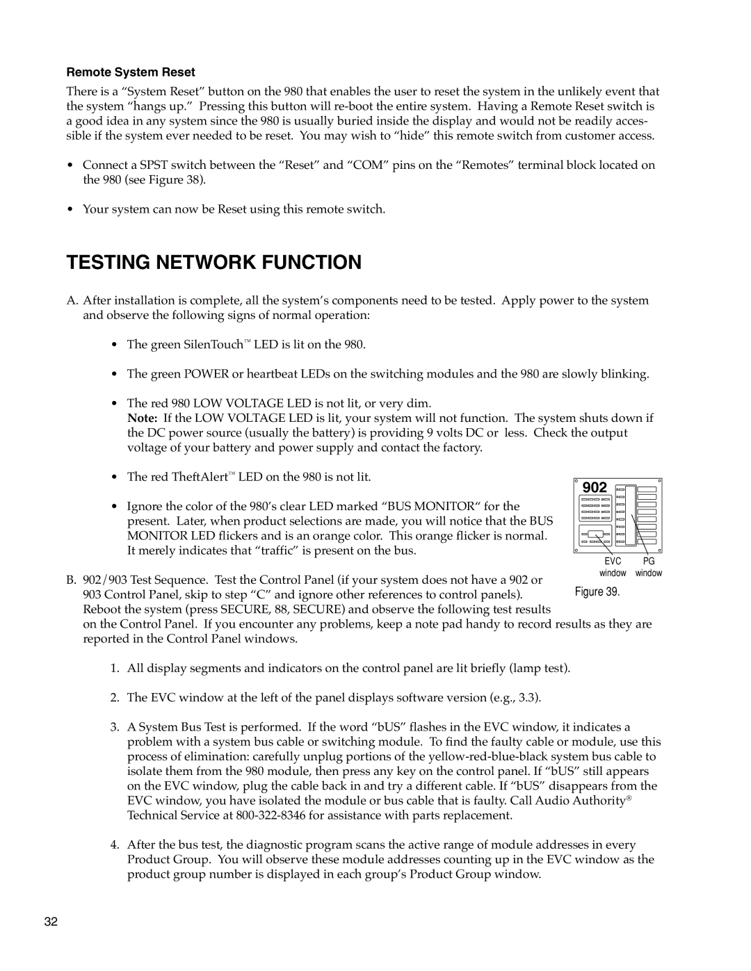
902
• Ignore the color of the 980’s clear LED marked “BUS MONITOR“ for the present. Later, when product selections are made, you will notice that the BUS MONITOR LED flickers and is an orange color. This orange flicker is normal. It merely indicates that “traffic” is present on the bus.
B. 902/903 Test Sequence. Test the Control Panel (if your system does not have a 902 or 903 Control Panel, skip to step “C” and ignore other references to control panels). Reboot the system (press SECURE, 88, SECURE) and observe the following test results
EVC PG window window
on the Control Panel. If you encounter any problems, keep a note pad handy to record results as they are reported in the Control Panel windows.
1.All display segments and indicators on the control panel are lit briefly (lamp test).
2.The EVC window at the left of the panel displays software version (e.g., 3.3).
3.A System Bus Test is performed. If the word “bUS” flashes in the EVC window, it indicates a problem with a system bus cable or switching module. To find the faulty cable or module, use this process of elimination: carefully unplug portions of the
4.After the bus test, the diagnostic program scans the active range of module addresses in every Product Group. You will observe these module addresses counting up in the EVC window as the product group number is displayed in each group’s Product Group window.
32