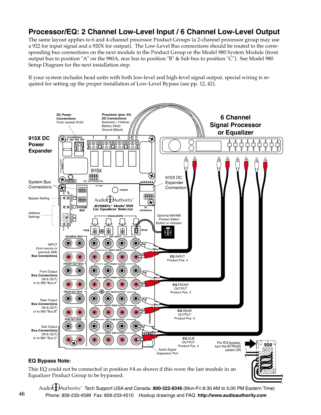
Processor/EQ: 2 Channel
The same layout applies to 6 and
If your system includes head units with both
| DC Power |
| Processor (pos. #4) | ||
| Connections |
| DC Connections |
| |
| From nearest 916X |
| Switched + (Yellow) |
| |
|
|
| Battery (Red) |
| |
|
|
| Ground (Black) |
| |
915X DC | BLK RED BLK RED | 1 | 2 | 3 | 4 |
| DC POWER BUS |
|
|
|
|
Power |
|
|
|
|
|
Expander |
|
|
|
|
|
| PUSH TO RESET | 915X |
|
| |
6 Channel
Signal Processor
or Equalizer
System Bus Connections
Bypass Setting
Address
Settings
| TRIPPED | DC EXPANSION |
|
|
| ||||
|
|
|
|
|
|
|
|
| |
|
| OFF |
|
|
|
|
| POWER |
|
ON |
|
| BYPASS |
|
|
|
|
| |
|
|
|
|
| ASD |
| |||
|
|
|
| GROUP | SYSTEM |
|
| Model 958 | DC |
|
|
|
|
| Car Equalizer Selector | ||||
|
|
|
|
| BUS | EXPANSION | |||
|
|
|
|
|
|
|
| ||
| 7 | 8 |
| ID |
|
| EQUALIZERS |
| |
6 | 9 | MODULE |
|
|
| ||||
5 |
|
| 0 |
|
|
|
|
| |
4 | 2 | 1 |
|
|
|
|
|
| |
| 3 |
|
|
|
|
|
|
| |
|
|
|
|
|
| 1 | 2 | 3 | 4 |
915X DC
Expander
Connection
Optional 994/995
Product Select
Button or Indicator
PSB |
EQ INPUT BUS
INPUT (from source or previous 958)
Bus Connections
LEFT INPUT
RIGHT INPUT
![]() PSB
PSB
S |
EQ INPUT
Product Pos. 4
FRONT OUT BUS | LEFT FRONT OUTPUT |
Front Output
Bus Connections
(IN & OUT) or to 980 "Bus A"
RIGHT FRONT OUTPUT
EQ FRONT
REAR OUT BUS![]() LEFT REAR OUTPUT
LEFT REAR OUTPUT
Rear Output |
| |
Bus Connections | RIGHT REAR OUTPUT | |
(IN & OUT) | ||
| ||
or to 980 "Bus B" |
| |
SUB OUT BUS | LEFT SUB OUTPUT | |
Sub Output |
| |
Bus Connections | RIGHT SUB OUTPUT | |
(IN & OUT) | ||
| ||
or to 980 "Bus C" |
|
EXPANSION
OUTPUT
Product Pos. 4
EQ REAR
OUTPUT
Product Pos. 4
EQ SUB |
|
|
OUTPUT | For EQ bypass, | 958 |
Product Pos. 4 | turn the BYPASS | |
Audio Signal | switch ON |
|
Expansion Port
EQ Bypass Note:
This EQ could not be connected in position #4 as shown if this were the last module in an Equalizer Product Group to be bypassed.
46 | ASD Tech Support USA and Canada: |
Phone: |
