User’s Manual
Alarm I/O & RS485
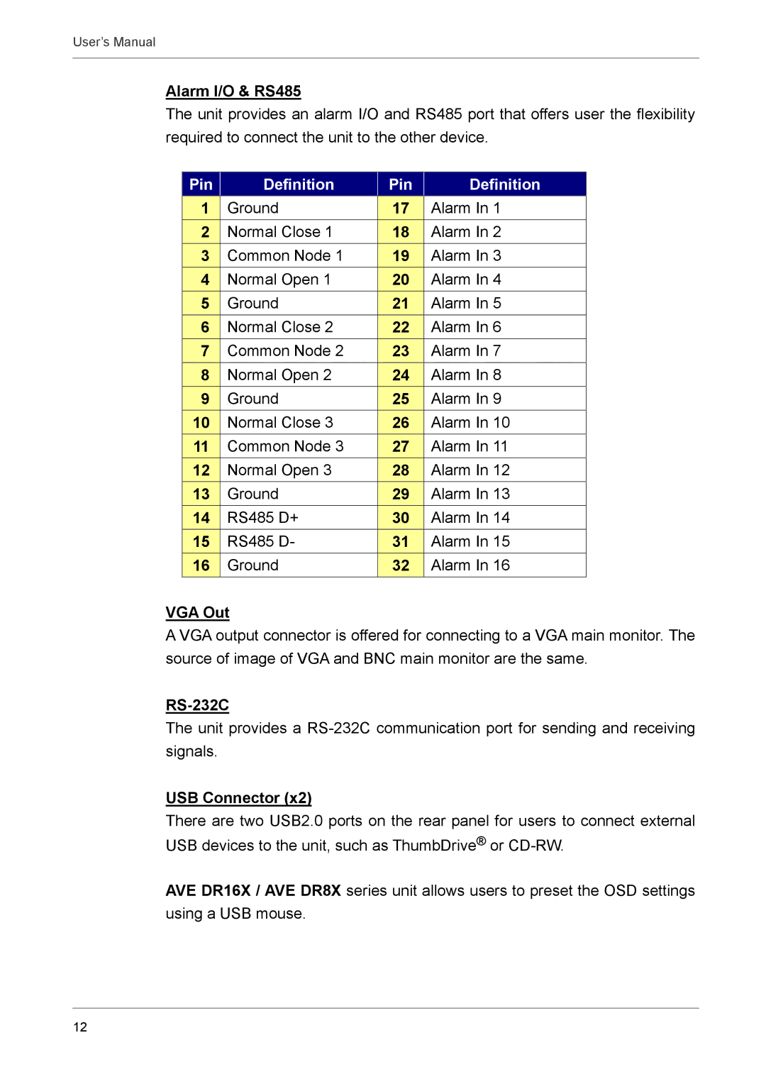
The unit provides an alarm I/O and RS485 port that offers user the flexibility required to connect the unit to the other device.
Pin |
| Definition |
| Pin |
| Definition |
1 |
| Ground |
| 17 |
| Alarm In 1 |
2 |
| Normal Close 1 |
| 18 |
| Alarm In 2 |
3 |
| Common Node 1 |
| 19 |
| Alarm In 3 |
4 |
| Normal Open 1 |
| 20 |
| Alarm In 4 |
5 |
| Ground |
| 21 |
| Alarm In 5 |
6 |
| Normal Close 2 |
| 22 |
| Alarm In 6 |
7 |
| Common Node 2 |
| 23 |
| Alarm In 7 |
8 |
| Normal Open 2 |
| 24 |
| Alarm In 8 |
9 |
| Ground |
| 25 |
| Alarm In 9 |
10 |
| Normal Close 3 |
| 26 |
| Alarm In 10 |
11 |
| Common Node 3 |
| 27 |
| Alarm In 11 |
12 |
| Normal Open 3 |
| 28 |
| Alarm In 12 |
13 |
| Ground |
| 29 |
| Alarm In 13 |
14 |
| RS485 D+ |
| 30 |
| Alarm In 14 |
15 |
| RS485 D- |
| 31 |
| Alarm In 15 |
16 |
| Ground |
| 32 |
| Alarm In 16 |
VGA Out
A VGA output connector is offered for connecting to a VGA main monitor. The source of image of VGA and BNC main monitor are the same.
RS-232C
The unit provides a
USB Connector (x2)
There are two USB2.0 ports on the rear panel for users to connect external USB devices to the unit, such as ThumbDrive® or
AVE DR16X / AVE DR8X series unit allows users to preset the OSD settings using a USB mouse.
12