INSTALLATION MANUAL | 17 |
4. Configuring the MAP450D
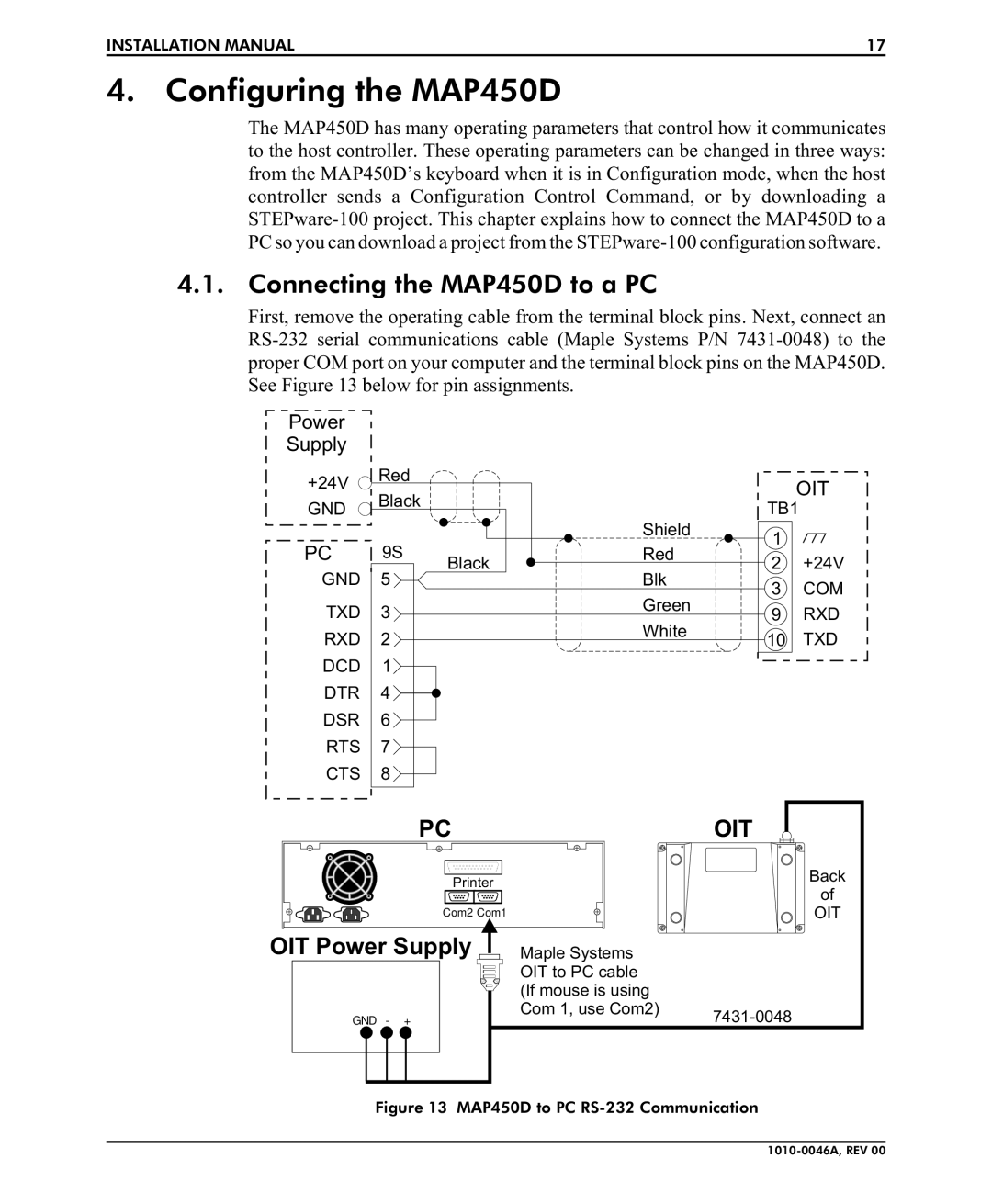
The MAP450D has many operating parameters that control how it communicates to the host controller. These operating parameters can be changed in three ways: from the MAP450D’s keyboard when it is in Configuration mode, when the host controller sends a Configuration Control Command, or by downloading a
4.1. Connecting the MAP450D to a PC
First, remove the operating cable from the terminal block pins. Next, connect an
Power
Supply
+24V | Red |
| |
GND | Black |
|
PC 9S Black GND 5
TXD 3
RXD 2
DCD 1
DTR 4
DSR 6
RTS 7
CTS 8
|
| OIT | |
| TB1 | ||
Shield | 1 |
| |
Red |
| ||
2 | +24V | ||
| |||
Blk | 3 | COM | |
| |||
Green | 9 | RXD | |
| |||
White | 10 | TXD | |
| |||
PC |
Printer |
Com2 Com1 |
OIT
Back
of
OIT
OIT Power Supply
GND - +
Maple Systems |
|
OIT to PC cable |
|
(If mouse is using |
|
Com 1, use Com2) | |
|
