2.3. RS-422/485 (Network mode)
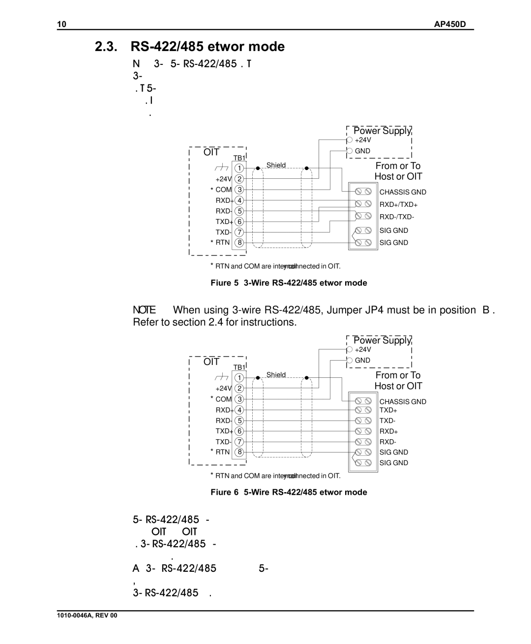
Network mode supports the 3-wire and 5-wire RS-422/485 configurations. The 3-wire configuration has both transmit and receive on the same pair of wires plus a signal common. The 5-wire configuration has differential signal pairs for transmit and receive plus a signal common. In both configurations the signal pairs must be twisted and surrounded by an overall shield.
OIT
| TB1 | |
| 1 | Shield |
| |
+24V | 2 | |
* COM | 3 | |
RXD+ | 4 | |
RXD- | 5 | |
TXD+ | 6 | |
TXD- | 7 | |
* RTN | 8 | |
*RTN and COM are internally connected in OIT.
Power Supply
+24V
GND
From or To
Host or OIT
CHASSIS GND
RXD+/TXD+
RXD-/TXD-
SIG GND
SIG GND
Figure 5 3-Wire RS-422/485 (Network mode)
NOTE: When using 3-wire RS-422/485, Jumper JP4 must be in position “B”. Refer to section 2.4 for instructions.
OIT
| TB1 | |
| 1 | Shield |
| |
+24V | 2 | |
* COM | 3 | |
RXD+ | 4 | |
RXD- | 5 | |
TXD+ | 6 | |
TXD- | 7 | |
* RTN | 8 | |
*RTN and COM are internally connected in OIT.
Power Supply
+24V
GND
From or To
Host or OIT
CHASSIS GND
TXD+
TXD-
RXD+
RXD-
SIG GND
SIG GND
Figure 6 5-Wire RS-422/485 (Network mode)
5-wire RS-422/485 supports full-duplex communications; which means that the host controller can trasmit data to the OITs and receive data from the OITs at the same time. 3-wire RS-422/485 only supports half-duplex communications; which means that the host controller cannot transmit and receive data at the same time. Although 3-wire RS-422/485 installations may be less costly than 5-wire installations, the increased complexity in programming the host controller for 3-wire RS-422/485 may increase development time.