INSTALLATION MANUAL | 13 |
The cable shield must not be used as the signal ground.
It is tempting to try and reduce the cost of
The signal ground must not be connected to the chassis or earth ground. The chassis or earth ground is intended as a safety ground for power supplies, EMI filters, voltage spike protection circuits, 120 VAC neutral returns, and all manner of AC and DC driven devices. As a result, the chassis or earth ground can carry large voltage potentials and currents. Connecting the signal ground to chassis or earth ground can damage the devices connected to the
2.4. Set Jumper for 3-Wire RS-422/485
This step is required only if the OIT will be communicating with the host controller using
JP4A
(Display)
B
(CPU Board)
JP4
A
B
| A |
| JP4 | ||
|
|
|
| ||
|
|
|
|
|
|
|
|
|
|
|
|
|
|
| B | ||
Position "A", | Position "B", | ||||
Normal | |||||
|
|
| RS485 | ||
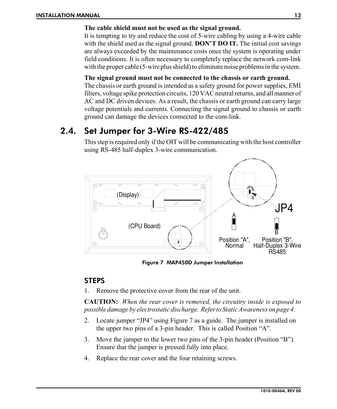
Figure 7 MAP450D Jumper Installation
STEPS
1.Remove the protective cover from the rear of the unit.
CAUTION: When the rear cover is removed, the circuitry inside is exposed to possible damage by electrostatic discharge. Refer to Static Awareness on page 4.
2.Locate jumper “JP4” using Figure 7 as a guide. The jumper is installed on the upper two pins of a
3.Move the jumper to the lower two pins of the
4.Replace the rear cover and the four retaining screws.