INSTALLATION MANUAL | 15 |
IMPORTANT: When panel mounting the MAP450D, do not catch the display connector on the panel cutout. The display is exposed while panel mounting and extra care should be taken. The display can be damaged if the display cable connector, which protrudes from the panel cutout, is touching the panel when tightened. To avoid damage, place the MAP450D gently onto the panel while monitoring for this condition.
3.2. Pedestal/Pendent Mount
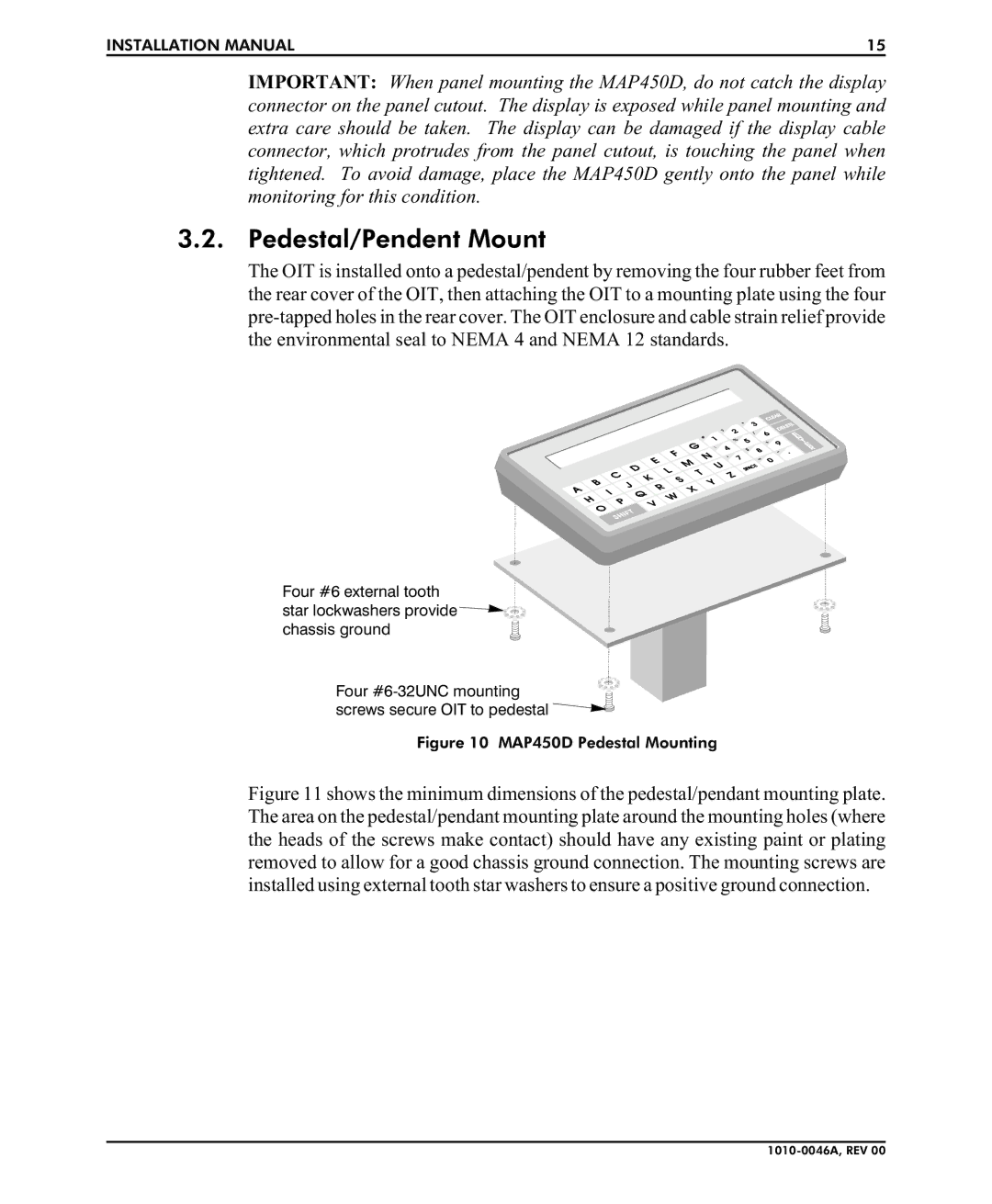
The OIT is installed onto a pedestal/pendent by removing the four rubber feet from the rear cover of the OIT, then attaching the OIT to a mounting plate using the four
Four #6 external tooth
star lockwashers provide ![]()
![]()
![]()
![]()
![]()
![]() chassis ground
chassis ground![]()
Four ![]()
![]()
![]()
![]()
![]() screws secure OIT to pedestal
screws secure OIT to pedestal ![]()
![]()