12 | MAP450D |
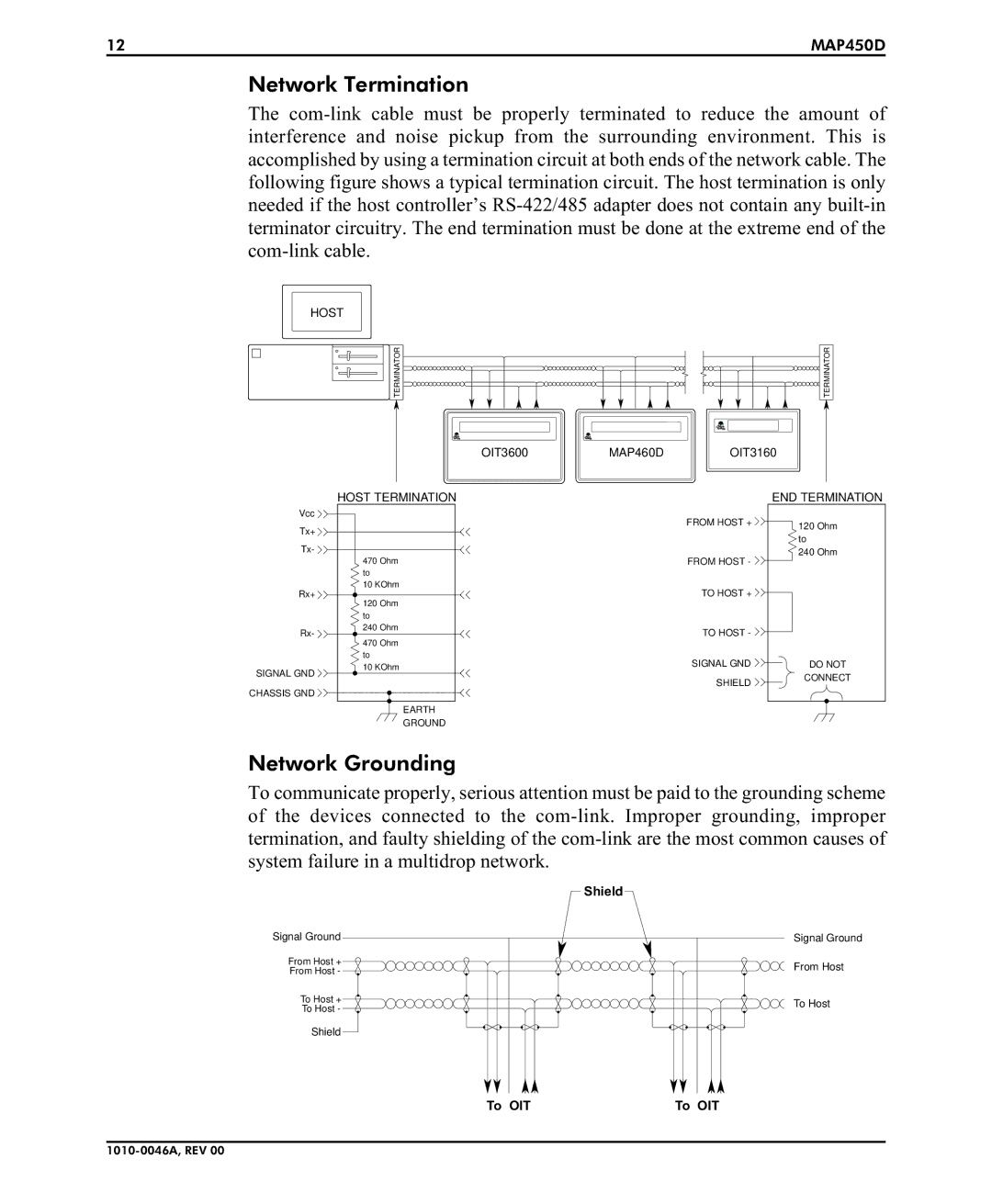
Network Termination
The
HOST
TERMINATOR | TERMINATOR |
OIT3600 | MAP460D | OIT3160 |
HOST TERMINATION
Vcc |
| |
Tx+ |
| |
Tx- |
| |
| 470 Ohm | |
| to | |
Rx+ | 10 KOhm | |
120 Ohm | ||
| ||
| to | |
Rx- | 240 Ohm | |
470 Ohm | ||
| ||
| to | |
SIGNAL GND | 10 KOhm | |
| ||
CHASSIS GND |
| |
| EARTH | |
| GROUND |
FROM HOST +
FROM HOST -
TO HOST +
TO HOST -
SIGNAL GND SHIELD
END TERMINATION
120Ohm
to
240Ohm
DO NOT
CONNECT
Network Grounding
To communicate properly, serious attention must be paid to the grounding scheme of the devices connected to the
| Shield | |
Signal Ground | Signal Ground | |
From Host + | From Host | |
From Host - | ||
| ||
To Host + | To Host | |
To Host - | ||
| ||
Shield |
| |
To OIT | To OIT |