8 | MAP450D |
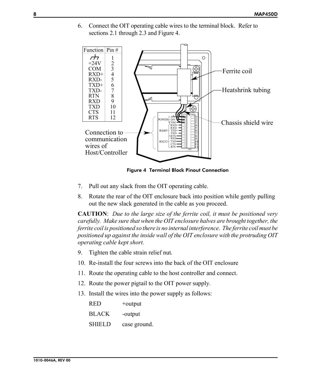
6.Connect the OIT operating cable wires to the terminal block. Refer to sections 2.1 through 2.3 and Figure 4.
Function Pin # |
|
|
|
| |
| 1 |
|
|
|
|
+24V | 2 |
|
|
|
|
COM | 3 |
|
|
| Ferrite coil |
RXD+ | 4 |
|
|
| |
|
|
|
| ||
RXD- | 5 |
|
|
|
|
TXD+ | 6 |
|
|
| Heatshrink tubing |
TXD- | 7 |
|
|
| |
RTN | 8 |
|
|
|
|
RXD | 9 |
|
|
|
|
TXD | 10 |
|
|
|
|
CTS | 11 |
|
|
|
|
RTS | 12 | POWER +24V | 1 |
| |
|
| 2 | Chassis shield wire | ||
|
|
| RXD+ | 4 | |
|
|
| COM | 3 |
|
|
|
| RXD- | 5 |
|
Connection to | RS485 | TXD+ | 6 |
| |
| TXD- | 7 |
| ||
communication | RS232 | RTN | 8 |
| |
TXD | 10 |
| |||
|
|
| RXD | 9 |
|
wires of |
|
| CTS | 11 |
|
|
| RTS | 12 |
| |
Host/Controller |
|
| TB1 |
| |
|
|
|
| ||
Figure 4 Terminal Block Pinout Connection
7.Pull out any slack from the OIT operating cable.
8.Rotate the rear of the OIT enclosure back into position while gently pulling out the new slack generated in the cable as you proceed.
CAUTION: Due to the large size of the ferrite coil, it must be positioned very carefully. Make sure that when the OIT enclosure halves are brought together, the ferrite coil is positioned so there is no internal interference. The ferrite coil must be positioned up against the inside wall of the OIT enclosure with the protruding OIT operating cable kept short.
9.Tighten the cable strain relief nut.
10.
11.Route the operating cable to the host controller and connect.
12.Route the power pigtail to the OIT power supply.
13.Install the wires into the power supply as follows:
RED +output
BLACK
SHIELD | case ground. |