INSTALLATION MANUAL | 7 |
2. Connecting the MAP450D to a Host Controller
It is necessary to follow all installation procedures described in this chapter for electrical noise immunity and CE compliance.
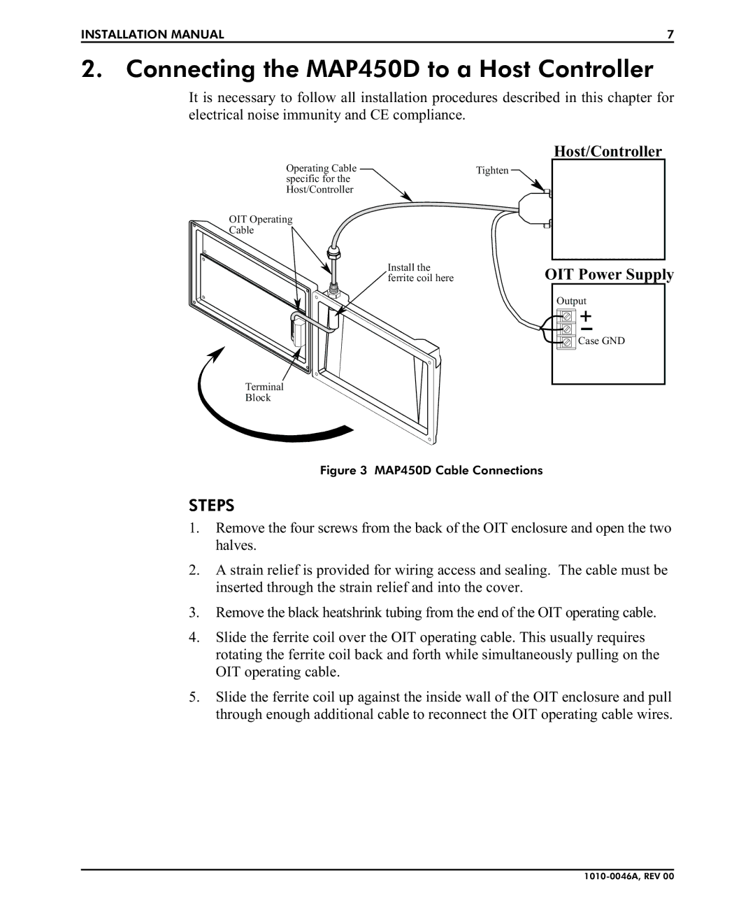
Host/Controller
Operating Cable | Tighten |
specific for the |
|
Host/Controller |
|
OIT Operating
Cable
Install the ferrite coil here
OIT Power Supply
Output
Case GND
Terminal
Block
Figure 3 MAP450D Cable Connections
STEPS
1.Remove the four screws from the back of the OIT enclosure and open the two halves.
2.A strain relief is provided for wiring access and sealing. The cable must be inserted through the strain relief and into the cover.
3.Remove the black heatshrink tubing from the end of the OIT operating cable.
4.Slide the ferrite coil over the OIT operating cable. This usually requires rotating the ferrite coil back and forth while simultaneously pulling on the OIT operating cable.
5.Slide the ferrite coil up against the inside wall of the OIT enclosure and pull through enough additional cable to reconnect the OIT operating cable wires.