REMOTE INTELLIGENT SENSOR - AREA MONITOR
SYSTEM OK icon confirms the system is operating normally.
NUMERICAL VALUE (in ppb or ppm) alternates with % value of remaining cassette life. When cassette is new the display reads 99%. As the tape is used, the numerical value reduces in proportion.
NOTE: If the system is turned off and then on at SW1, or if the tape reset button is used, the tape counter is reset to 99%. This occurs despite the actual tape remaining.
3.7.2SYSTEM NORMAL, GAS CONCENTRA- TION ABOVE THE ALARM THRESHOLD. Besides the SYSTEM OK and the NUMERICAL VALUE of the measured concentration, a ‘FLASH- ING BELLS’ icon is shown across the top of the display. This provides a strong visual warning that a Gas Alarm is present. The display is maintained during the period that the threshold level is ex- ceeded and until a complete sample period has passed where the concentration falls below the alarm level.
3.7.3OVER RANGE ALARM. When the moni- tored concentration exceed the system range, the ‘flashing bells’ icon is accompanied by the numerical readout displaying 9999 (ppb models) or 99.99 (ppm models).
3.7.4SYSTEM FAULT. When self diagnostics detect a fault condition, the SYSTEM OK icon is turned off and one or more fault icons are dis- played. Icons and their meaning are as follows:
Constant
This symbol shows that the input supply has failed, or is not connected, and the system is operating from the internal
Flashing
Shows that the
Constant
Warns that the cassette has run out of tape, or the tape has broken, or the tape gate has been left open.
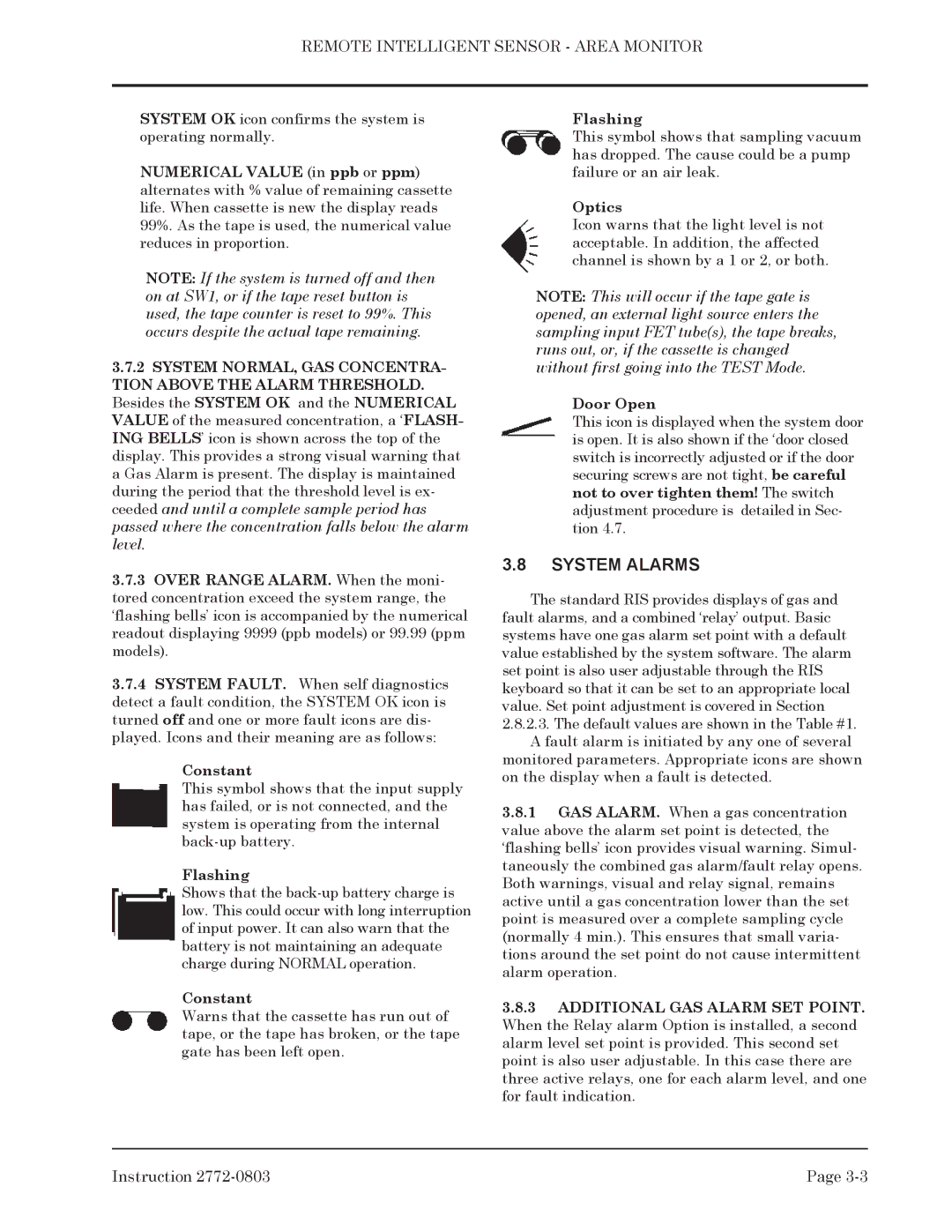
Flashing
This symbol shows that sampling vacuum has dropped. The cause could be a pump failure or an air leak.
Optics
Icon warns that the light level is not acceptable. In addition, the affected channel is shown by a 1 or 2, or both.
NOTE: This will occur if the tape gate is opened, an external light source enters the sampling input FET tube(s), the tape breaks, runs out, or, if the cassette is changed without first going into the TEST Mode.
Door Open
This icon is displayed when the system door is open. It is also shown if the ‘door closed switch is incorrectly adjusted or if the door securing screws are not tight, be careful not to over tighten them! The switch adjustment procedure is detailed in Sec- tion 4.7.
3.8SYSTEM ALARMS
The standard RIS provides displays of gas and fault alarms, and a combined ‘relay’ output. Basic systems have one gas alarm set point with a default value established by the system software. The alarm set point is also user adjustable through the RIS keyboard so that it can be set to an appropriate local value. Set point adjustment is covered in Section
2.8.2.3.The default values are shown in the Table #1. A fault alarm is initiated by any one of several
monitored parameters. Appropriate icons are shown on the display when a fault is detected.
3.8.1GAS ALARM. When a gas concentration value above the alarm set point is detected, the ‘flashing bells’ icon provides visual warning. Simul- taneously the combined gas alarm/fault relay opens. Both warnings, visual and relay signal, remains active until a gas concentration lower than the set point is measured over a complete sampling cycle (normally 4 min.). This ensures that small varia- tions around the set point do not cause intermittent alarm operation.
3.8.3ADDITIONAL GAS ALARM SET POINT. When the Relay alarm Option is installed, a second alarm level set point is provided. This second set point is also user adjustable. In this case there are three active relays, one for each alarm level, and one for fault indication.
Instruction | Page |